Airtight container manufacturing method, and image displaying apparatus manufacturing method using airtight container manufacturing method

a manufacturing method and airtight container technology, applied in the manufacture of electrode systems, electric discharge tubes/lamps, lamination ancillary operations, etc., can solve the problems of reducing bonding intensity and difficulty in effectively using energy, and achieve the desired bonding intensity, improve the “takt time” in manufacture, and effectively utilize energy beam

Inactive Publication Date: 2014-02-04
CANON KK
View PDF13 Cites 0 Cited by
  • Summary
  • Abstract
  • Description
  • Claims
  • Application Information

AI Technical Summary

Benefits of technology

[0009]That is, an object of the present invention is to provide a manufacturing method of an airtight container, to be used to manufacture the glass envelope, which enables to improve the “takt time” in manufacture as enabling to effectively utilize the energy beam and also acquire desired bonding intensity.
[0012]In consequence, the present invention enables to improve the “takt time” in the manufacture as enabling to effectively utilize the energy beam and also acquire the desired bonding intensity.

Problems solved by technology

For this reason, since the energy does not reach the frit glass acting as a bonding material, there is a problem that it is difficult to effectively utilize the energy.
For this reason, there is a problem that bonding intensity decreases according as an area in which excellent bonding can be acquired decreases.

Method used


Image

  • Airtight container manufacturing method, and image displaying apparatus manufacturing method using airtight container manufacturing method
  • Airtight container manufacturing method, and image displaying apparatus manufacturing method using airtight container manufacturing method
  • Airtight container manufacturing method, and image displaying apparatus manufacturing method using airtight container manufacturing method

Examples


embodiment 1

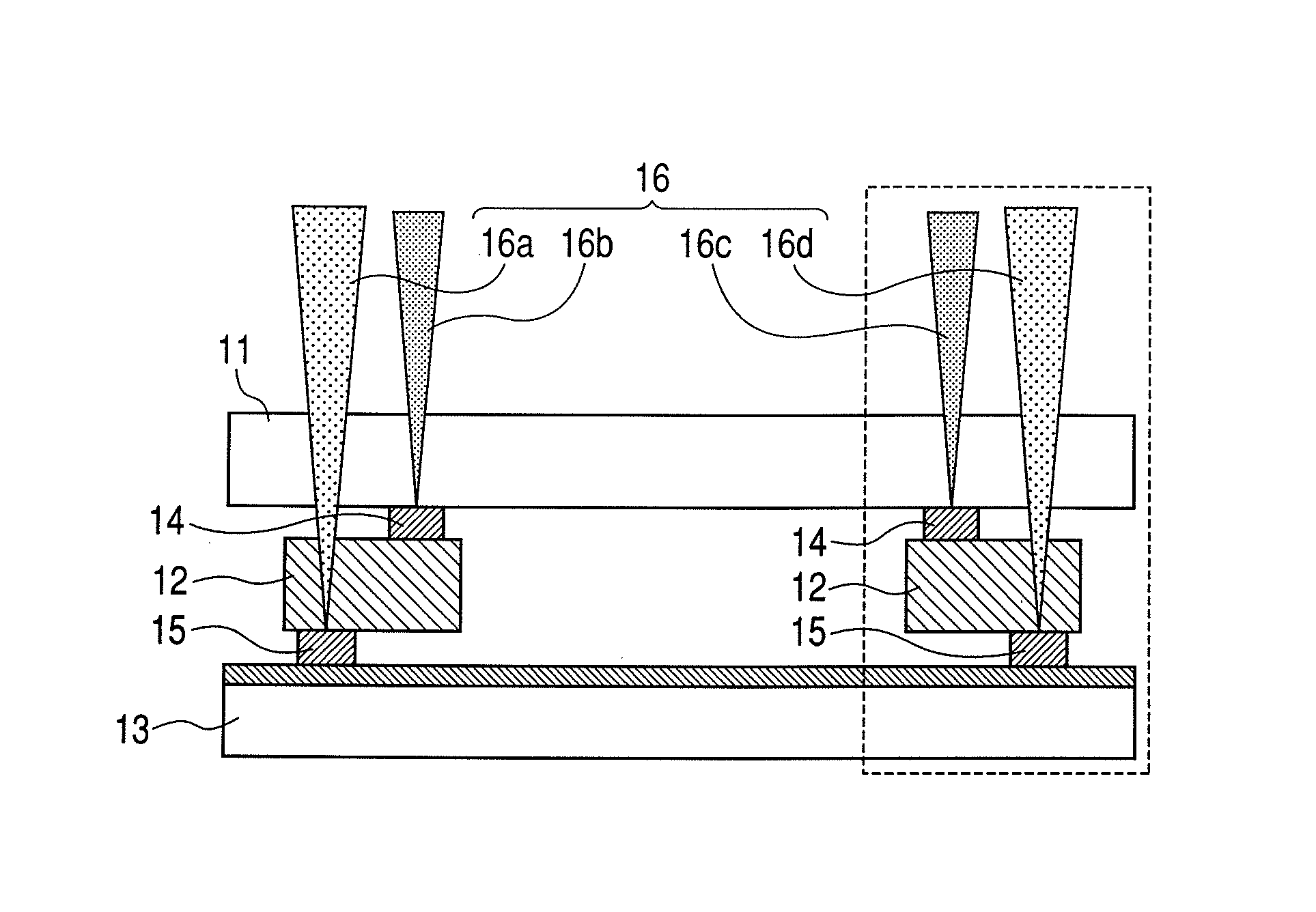
[0069]In the manufacturing method of the airtight container according to the present invention, as illustrated in FIGS. 1A and 1B, a thin film device, wirings, an insulation material and other materials are first formed on a high distortion point glass substrate having a diagonal line of 7 inches, thereby forming the first plate structure and the second plate structure. Here, the thin film device is the device for constituting the displaying device, the wirings are to transmit signals for driving the thin film device, and the insulation material is to secure insulation between the wirings and the bonding material.

[0070]Incidentally, each of the first and second plate structures, which are applied for an existing a flat surface displaying apparatus, is used as it is. Further, the operation process before each of the first and second plate structures is sealed is the same as the existing process to be used in the conventional technique.

[0071]Subsequently, the frame of which the width ...

embodiment 2

[0079]The arrangement and the alignment are performed as well as Embodiment 1, and only one laser beam is used for simplifying the apparatus.

[0080]As illustrated in FIG. 9, the spot is arranged so that the center of the spot is the end of the first bonding material and that the half of the spot area is irradiated to the second bonding material 15, and the laser beam is moving-irradiated as well as Embodiment 1, thereby forming the airtight container. At this time, the energy utilization efficiency of the laser beam in the bonding by the second bonding material is 10%. Further, as well as Embodiment 1, the bonding is performed uniformly. Furthermore, even if the completed airtight container is baked at 300° C., any exfoliation does not occur, and the bonding is excellently maintained.

embodiment 3

[0081]Two semiconductor lasers of which the wavelengths are equivalent to that of a near infrared ray are used as the energy beams to be irradiated to the work arranged as well as Embodiment 1. Further, the spot of one of these beams is arranged so as to be wholly held in the first bonding material, and the spot the other of these beams is arranged in the vicinity of the center of the second bonding material so as to be wholly held in the second bonding material. Then, the laser beam is moving-irradiated as well as Embodiment 1, thereby forming the airtight container. At this time, the energy utilization efficiency of the laser beam in the bonding by the second bonding material is 20%. Further, as well as Embodiment 1, the bonding is performed uniformly. Furthermore, since the bonding width is wider than that in Embodiment 1, it is possible to solidify the bonding. In any case, even if the completed airtight container is baked at 300° C., any exfoliation does not occur, and the bond...


PUM

PropertyMeasurementUnit
thicknessaaaaaaaaaa
thicknessaaaaaaaaaa
widthaaaaaaaaaa

Abstract

A manufacturing method provides an airtight container having a first plate structure, a second plate structure having a wiring formed on a surface facing the first plate structure, a frame arranged between the first plate structure and the second plate structure, a first bonding material arranged between the first plate structure and the frame, and a second bonding material arranged between the second plate structure and the frame. The method includes the steps of bonding the first plate structure and the frame by irradiating a first energy beam to the first bonding material by transmitting the first energy beam through the first plate structure, and bonding the second plate structure and the frame by irradiating a second energy beam to the second bonding material by transmitting the second energy beam through the first plate structure and the frame. The first energy beam and the second energy beam are scanned in close proximity to each other and at the same speed.

Description

BACKGROUND OF THE INVENTION[0001]1. Field of the Invention[0002]The present invention relates to an airtight container, and a manufacturing method of an image displaying apparatus using the airtight container.[0003]2. Description of the Related Art[0004]As one example of a method of manufacturing an airtight glass envelope in which vacuum is maintained, there is a method in which a frit glass is used. In this method, the frit glass acting as a sealant is applied or set between respective glass members such as a face plate, a rear plate and an outer frame. Then, in such a state, the acquired subject matter is entered into a sealing furnace such as an electric furnace or the like or set on a hot plate (or interposed between the upper hot plate and the lower hot plate), and the entire subject matter (that is, the face plate, the rear plate and the outer frame) is heated up to a sealing temperature. Thus, since the frit glass is melted by this heating, the face plate and the outer frame...

Claims


Application Information

Patent Timeline
Patent Type & Authority Patents(United States)
IPC IPC(8): B29C65/00
CPCH01J9/261
Inventor OHASHI, YASUONAKAZAWA, TOMONORIKURACHI, KOSUKETAGAWA, MASAHIROHASEGAWA, MITSUTOSHI
Owner CANON KK
Why Eureka
Try Eureka