Arrangement for a removable ion-optical assembly in a mass spectrometer

a technology of mass spectrometer and ion-optical assembly, which is applied in the direction of curtain suspension device, particle separator tube details, separation process, etc., can solve the problem of ion beam not being accurately focused onto the detector, interfering with the acceleration process, and affecting the focusing properties of the accelerating electrode, etc. problems, to achieve the effect of facilitating the insertion of the counterpart, accurate alignment of the ion-optical assembly member, and facilitating

Active Publication Date: 2014-02-04
BRUKER DALTONIK GMBH & CO KG
View PDF11 Cites 2 Cited by
  • Summary
  • Abstract
  • Description
  • Claims
  • Application Information

AI Technical Summary

Benefits of technology

[0019]The small spatial size of the points via which the support elements engage with each other, by a simple small contact area, for example, facilitates the removal and reinsertion of the mount into the receptacle, particularly because of the low friction resistances. The small number of contact points, furthermore, makes it possible to satisfy the high demands in terms of reducing material abrasion in a vacuum environment, which can be caused by a relative motion of two touching surfaces.
[0033]In further embodiments, the mount has an inner aperture, and the ion-optical assembly member comprises a body which is slightly undersized to fit into the inner aperture. This allows easy insertion of the ion-optical assembly member into the mount. The ion-optical assembly member may further comprise a flange portion protruding from the body as to contact a rim region of the inner aperture when engaging therewith.
[0034]In some embodiments, the flange portion is doubly stepped as to provide alignment surfaces for contacting corresponding counter-surfaces at the receptacle. Such design allows for accurate alignment of the ion-optical assembly member in relation to the receptacle without suffering from any mechanical tolerance at interfaces with the mount. The counter-surfaces may be located at a groove portion of the receptacle. Preferably, the groove portion has a beveled entrance to facilitate insertion of the counterpart at the ion-optical assembly member and to assist in the disengaging step.
[0035]In various embodiments, a direction of insertion and withdrawal is approximately perpendicular to an axis of the receptacle, which preferably coincides with an ion path (axis) in a mass spectrometer. Such direction generally represents the shortest way of withdrawing something from a mass spectrometer thereby facilitating compact construction of the whole assembly.

Problems solved by technology

This interferes with the acceleration process.
Field changes, in particular, interfere with the focusing properties of the accelerating electrodes.
Consequently, the ion beam is no longer focused accurately onto the detector.
The reduction in the ion throughput also limits the number of analyses which are possible per sample, and reduces the detection limit of the mass spectrometer.
However, this method only addresses the symptoms of the loss of throughput in the ion source, and promises only a short-term effect.
Since the confined space makes it difficult to clean the ion-optical assembly while it is inside the mass spectrometer, and the aim is to avoid contaminating neighboring components with the dirt removed during the cleaning process, the ion-optical assembly is usually uninstalled.
If the mass spectrometer is vented during the disassembly, it often takes some hours until the necessary operating vacuum is restored after the ion-optical assembly has been cleaned and re-inserted.
It becomes difficult, however, when the removed parts have to be reinserted in their position in the mass spectrometer.
The man-hours required for such maintenance work are considerable, and also costly for the user of the mass spectrometer, who must pay the travel expenses of the specialist personnel, for example.

Method used


Image

  • Arrangement for a removable ion-optical assembly in a mass spectrometer
  • Arrangement for a removable ion-optical assembly in a mass spectrometer
  • Arrangement for a removable ion-optical assembly in a mass spectrometer

Examples


Embodiment Construction

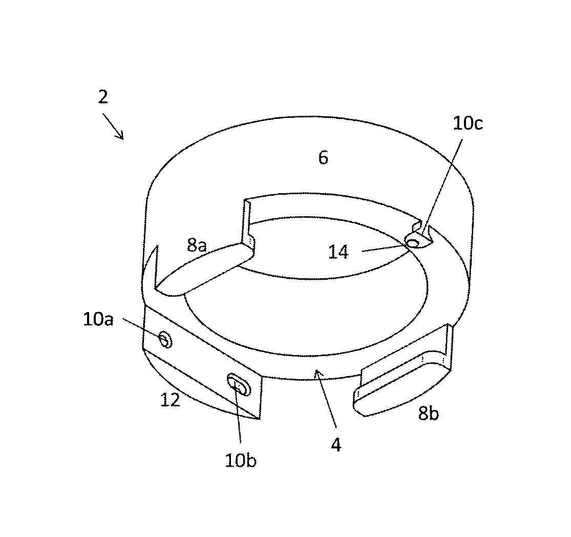
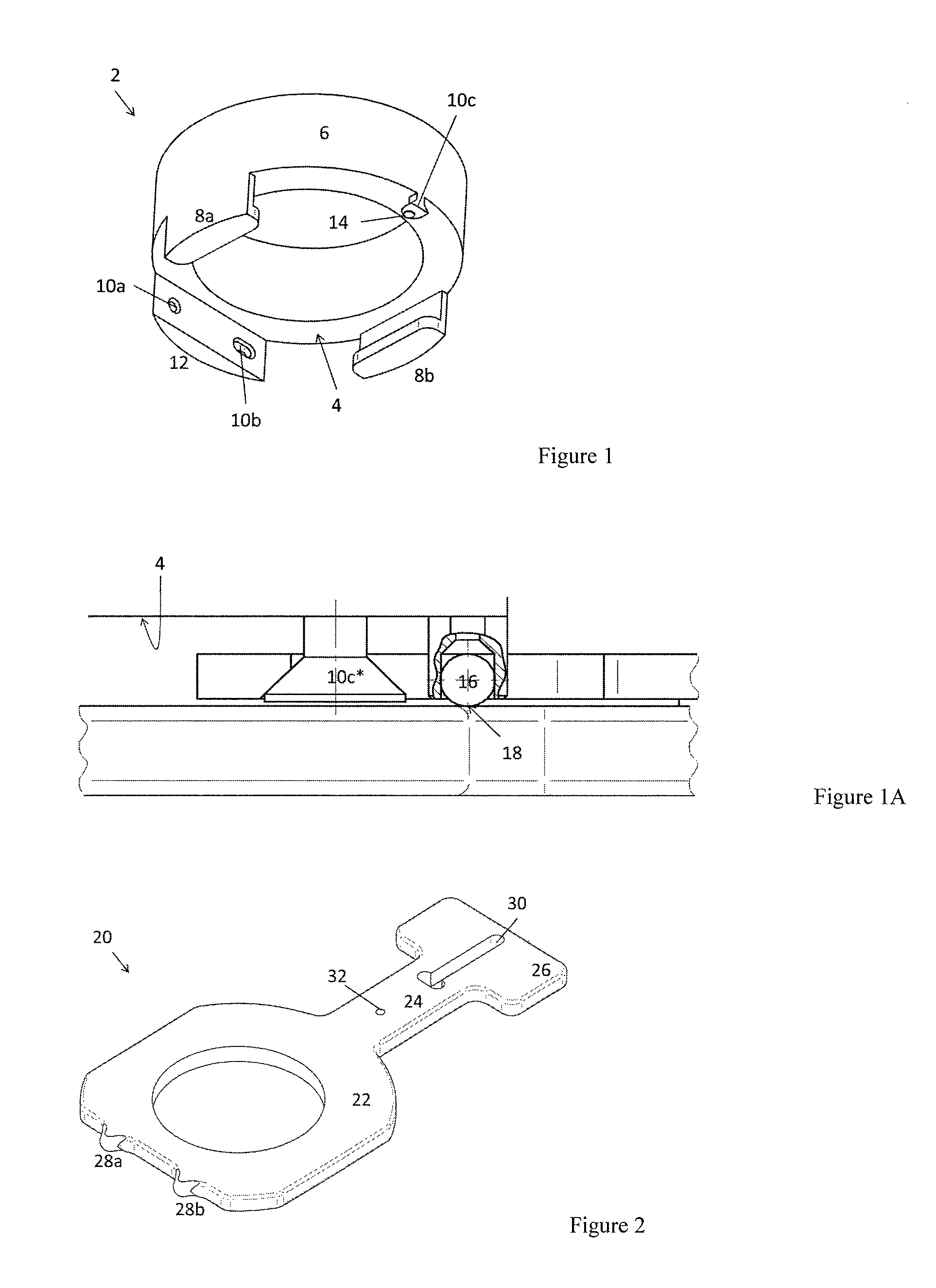
[0054]FIG. 1 shows an embodiment of a receptacle 2. The receptacle 2 has a cylindrical basic structure. On one end 4 of the cylinder 6, two angled elements 8a, 8b are arranged diametrically opposite each other in this example and serve as guide elements for the mount, which will be described in connection with another illustration. Roughly along a line which is at right angles to the line connecting the angled elements 8a, 8b, there are three support elements 10a, 10b, 10c, which are approximately diametrically opposite each other on the end 4 of the cylinder 6. The three support elements 10a, 10b, 10c define a support plane, onto which a mount is aligned with the receptacle 2 when inserted.

[0055]One support element 10a is formed by a sunken hole; another support element 10b by a recessed pocket in a shoulder piece 12 arranged on the end face 4 so as to be open toward the cylinder axis. The cylinder axis (not shown) can preferably correspond to an ion path when used in the operation...


PUM


Abstract

A device for use in a mass spectrometer allows an ion-optical assembly to be removed, cleaned and reinserted with relatively high positioning accuracy. In particular, the device obviates the need for complex adjustments requiring special knowledge after the reinsertion. The objective is achieved by an arrangement comprising a receptacle and a mount for a removable ion-optical assembly in a mass spectrometer. Favorable implementations provide a mount and a receptacle with three pairs of complementary support elements, the three support elements on the receptacle form a support plane, and, when the mount is inserted into the receptacle, at least two pairs of support elements are engaged and the mount is aligned with respect to the support plane with the aid of the third pair of support elements.

Description

PRIORITY INFORMATION[0001]This patent application claims priority from German Patent Application 10 2011 109 397.8 filed on Aug. 4, 2011, which is hereby incorporated by reference.FIELD OF THE INVENTION[0002]The invention relates to an arrangement comprising a receptacle and a mount for a removable ion-optical assembly in a mass spectrometer, and a mass spectrometer with a corresponding arrangement.BACKGROUND OF THE INVENTION[0003]The performance of a mass spectrometer can be reduced by contamination of its components, such as ion sources. During operation of a MALDI desorption ion source, for example, a sometimes visible coating of organic material can build up on the electrodes. In the prior art, such coatings on ion-optical devices in mass spectrometers are described by Girard et al. in the Journal of Chromatography Science, 2010 October, 48 (9), 778-779, and in the article by Kenneth L. Busch entitled “Ion Burn and the Dirt of Mass Spectrometry”, online publication, Sep. 1, 2010...

Claims


Application Information

Patent Timeline
Patent Type & Authority Patents(United States)
IPC IPC(8): B01D59/44H01J49/00
CPCH01J49/02H01J49/068
Inventor KERN, EWGENIJREBETTGE, JENS
Owner BRUKER DALTONIK GMBH & CO KG
Why Eureka
Try Eureka