
Electrophoretic display driving approaches

a technology of electrophoretic display and driving scheme, which is applied in the direction of instruments, electric digital data processing, computing, etc., can solve the problems of reverse bias, degradation of image-retention characteristics of epd b>100/b>, and difficulty in implementing solutions and high cos

Active Publication Date: 2014-02-04
E INK CORPORATION
View PDF132 Cites 70 Cited by
  • Summary
  • Abstract
  • Description
  • Claims
  • Application Information

AI Technical Summary

Benefits of technology

The present invention relates to an improved driving scheme for an electrophoretic display (EPD). The technical effect of this invention is to prevent the reverse bias condition in the EPD, which can affect display quality by causing charged pigment particles in affected cells to migrate away from the position to which they have been driven. The invention provides a driving scheme that reduces the impact of reverse bias on display quality.

Problems solved by technology

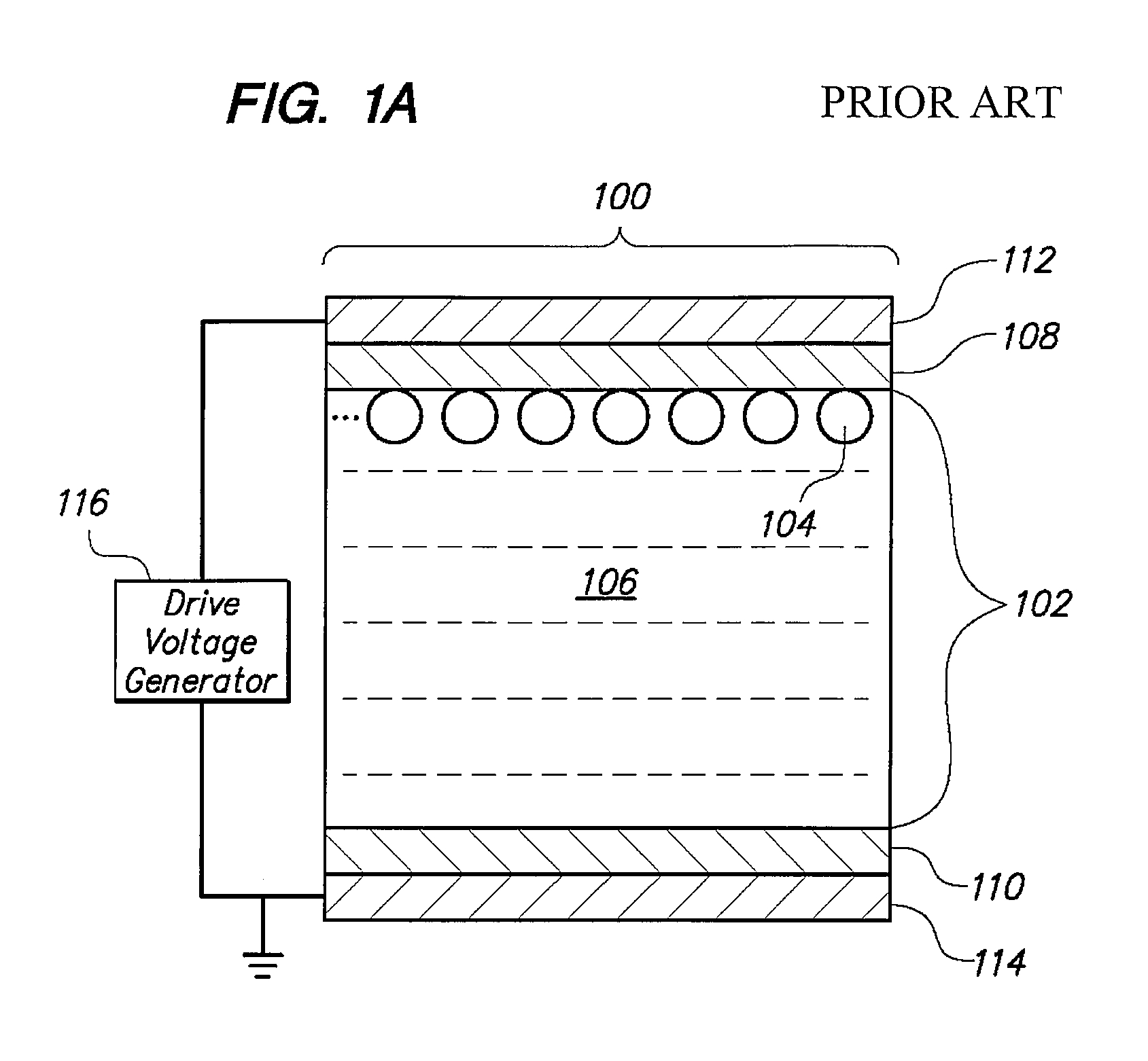
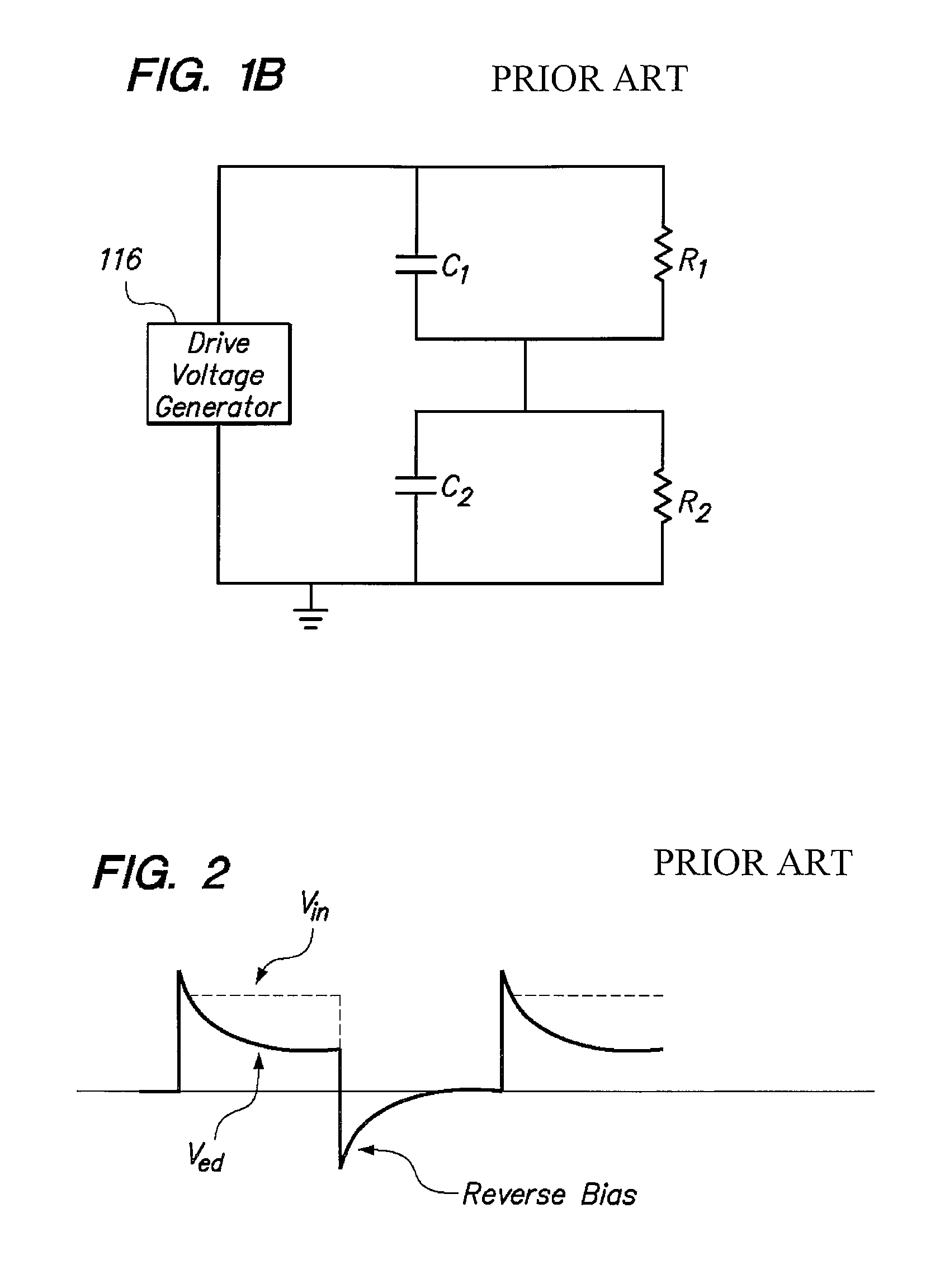
One problem associated with these EPDs is reverse bias.
This “undershooting”, representing the reverse bias condition, causes charged particles to migrate away from a position to which they have been driven and results in degradation of the image-retention characteristics of the EPD 100.
However, this solution is difficult and costly to implement.

Method used


Image

  • Electrophoretic display driving approaches
  • Electrophoretic display driving approaches
  • Electrophoretic display driving approaches

Examples


Embodiment Construction

[0040]The present invention can be implemented in numerous ways, including as a process, an apparatus, a system, or a computer readable medium such as a computer readable storage medium or a computer network wherein program instructions are sent over optical or electronic communication links. The order of the steps of disclosed processes may be altered within the scope of the invention.

[0041]A detailed description of one or more preferred embodiments of the invention is provided below with drawing figures that illustrate by way of example the principles of the invention. While the invention is described in connection with such embodiments, it should be understood that the invention is not limited to any embodiment. On the contrary, the scope of the invention is limited only by the appended claims and the invention encompasses numerous alternatives, modifications and equivalents. For the purpose of example, numerous specific details are set forth in the following description in order...


PUM


Abstract

A system and method are disclosed for reducing reverse bias in an electrophoretic display. The system and method include the application of varying levels of voltages across an array of electrophoretic display cells of the electrophoretic display to move the cells towards a stable state in a driving cycle. In addition, the system and method disconnect the voltages from the electrophoretic display cells at a time duration prior to reaching step transitions of the voltages during the driving cycle. Pre-driving approaches apply a first pre-driving voltage at a first polarity to the display cells before driving the display cells with a second driving voltage at a second, opposite polarity. Varying the time duration and amplitude of the pre-driving signals produces further beneficial reduction in reverse bias.

Description

CROSS-REFERENCE TO RELATED APPLICATIONS; PRIORITY CLAIM[0001]This application claims domestic priority under 35 U.S.C. §120 as a Continuation of U.S. application Ser. No. 10 / 973,810, filed Oct. 25, 2004, the entire contents of which is hereby incorporated into this application by reference for all purposes as if fully set forth herein.FIELD OF THE INVENTION[0002]The present invention relates generally to electrophoretic displays. More specifically, an improved driving scheme for an electrophoretic display is disclosed.BACKGROUND OF THE INVENTION[0003]The electrophoretic display (EPD) is a non-emissive device based on the electrophoresis phenomenon of charged pigment particles suspended in a solvent. It was first proposed in 1969. The display usually comprises two plates with electrodes placed opposing each other, separated by using spacers. One of the electrodes is usually transparent. A suspension composed of a colored solvent and charged pigment particles is enclosed between the t...

Claims


Application Information

Patent Timeline
Patent Type & Authority Patents(United States)
IPC IPC(8): G09G3/34
CPCG09G2310/0275G09G3/344G09G2320/0257
Inventor CHUNG, JERRYWANG, WANHENGCHEN, YAJUANYAO, WEIHOU, JACKCHU, LI-YANG
Owner E INK CORPORATION
Learn More