
Temperature controlled voltage conversion device

a voltage conversion device and temperature control technology, applied in the direction of ignition automatic control, process and machine control, instruments, etc., can solve the problems of high tendency to overheat, inability to prevent the overheating of filtering capacitors or reactors, and inability to prevent the overheating of filtering capacitors. achieve the effect of reducing the voltage conversion ratio preventing the overheating of the reactor of the dc-dc converter

Active Publication Date: 2014-02-04
DENSO CORP
View PDF24 Cites 5 Cited by
  • Summary
  • Abstract
  • Description
  • Claims
  • Application Information

AI Technical Summary

Benefits of technology

The present invention provides a voltage conversion device that prevents overheating of a capacitor and a reactor of a DC-DC converter. The device includes a cooling unit and a temperature detecting unit that detects the temperature of the cooling medium. A switching unit converts direct current power based on the energy accumulated in the reactor and the cooling medium temperature. A switching controller controls the switching operation of the switching element based on the set switching frequency to control the voltage conversion ratio of the DC-DC converter. This invention is useful for voltage conversion devices that use a DC-DC converter.

Problems solved by technology

However, when the switching frequency of the switching element is reduced, although the temperature increase of the switching element is suppressed, the ripple component of the current flowing through a reactor is increased, and consequently the extent of temperature increase due to the ripple current of the reactor is increased, resulting in a higher tendency to overheat.
Furthermore, when the filtering capacitor is provided in parallel with the direct current power supply, if the switching frequency of the switching element is reduced, the ripple current flowing through the filtering capacitor is also increased, and consequently the extent of temperature increase due to the ripple current of the filtering capacitor is increased, resulting in a higher tendency to overheat.
Because of this, although the overheating of the switching element can be suppressed by changing the switching frequency of the switching element according to the temperature of the switching element, it is not possible to prevent the overheating of the filtering capacitor or the reactor.

Method used


Image

  • Temperature controlled voltage conversion device
  • Temperature controlled voltage conversion device
  • Temperature controlled voltage conversion device

Examples


Embodiment Construction

[0025]A preferred embodiment of the present invention will now be described in detail with reference to the drawings.

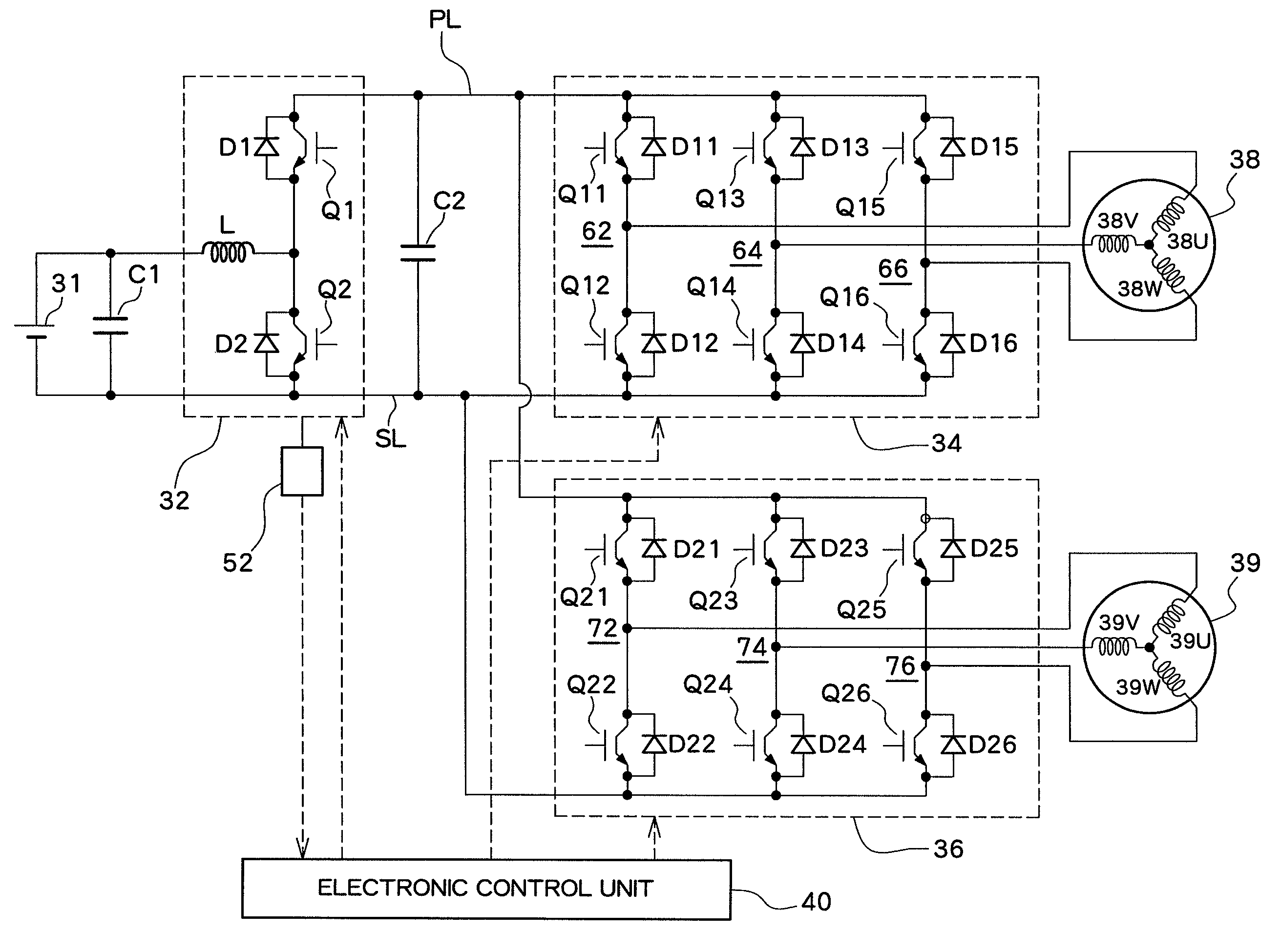
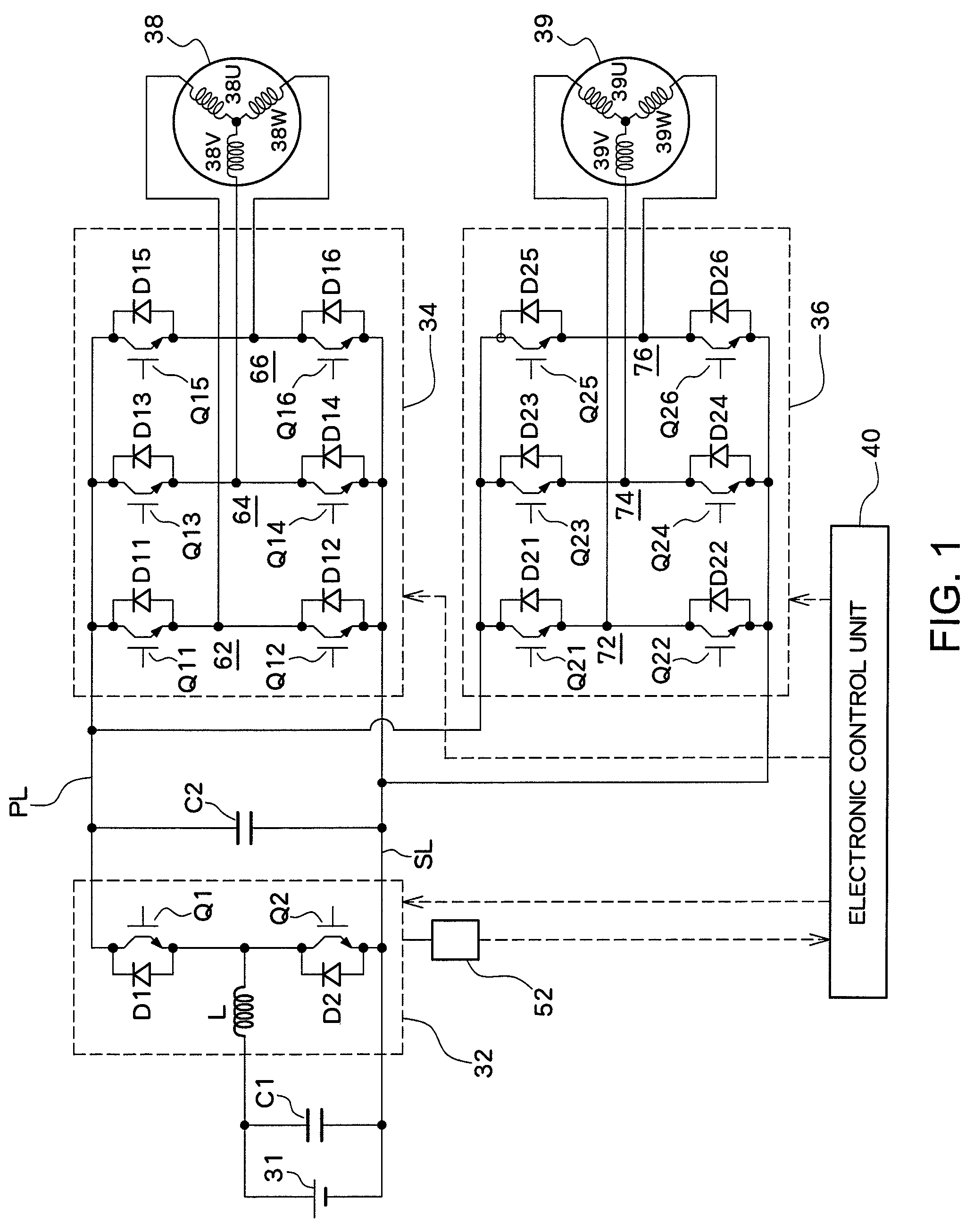
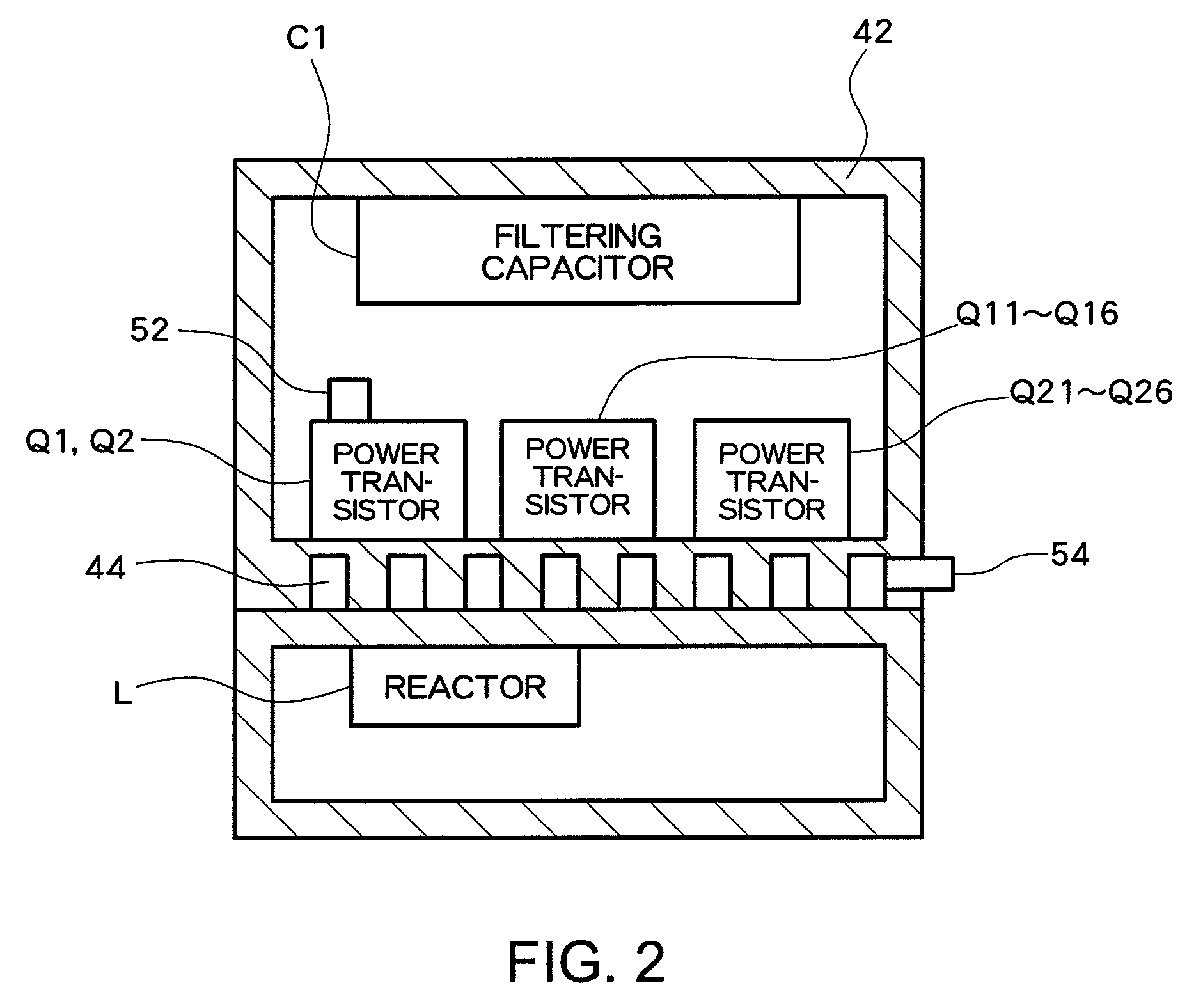
[0026]FIG. 1 is a diagram schematically showing a structure of a motor driving system having a voltage conversion device according to a preferred embodiment of the present invention. A motor driving system related to the present embodiment may be used as, for example, a driving system of a vehicle, and, as shown in FIG. 1, comprises a secondary battery 31 which is a direct current power supply which can be charged and discharged, a DC-DC converter 32 which converts direct current power from the secondary battery 31 to direct current power of a different voltage value and outputs the converted power, a filtering capacitor C1 which is provided at an input side of the DC-DC converter 32, inverters 34 and 36 which convert the direct current power from the DC-DC converter 32 to an alternating current and output the converted power, an averaging capacitor C2 provided at inp...


PUM


Abstract

A switching frequency setting unit sets switching frequency of a switching element, based on both the temperature of a cooling medium which cools a DC-DC converter and the temperature of a switching element of the DC-DC converter. A switching controller controls the voltage conversion ratio of the DC-DC converter by controlling switching operation of the switching element at the set switching frequency.

Description

TECHNICAL FIELD[0001]The present invention relates to a voltage conversion device which converts direct current power from a direct current power supply into direct current power of a different voltage value utilizing a switching operation of a switching element, and outputs the converted power.BACKGROUND ART[0002]JP 2001-8441 A discloses related art of a voltage conversion device of this type. A voltage conversion device of Patent Document 1 is a DC-DC converter which converts direct current power from a secondary battery (direct current power supply) to direct current power of a different voltage value utilizing a switching operation of a transistor and outputs the converted power, and the cycle of the pulse applied to the transistor is changed based on a temperature around the DC-DC converter.[0003]In a DC-DC converter, in some cases, a capacitor (filtering capacitor) is provided at the input side in parallel with the direct current power supply (secondary battery). During a swit...

Claims


Application Information

Patent Timeline
Patent Type & Authority Patents(United States)
IPC IPC(8): H05K7/20H02M3/156
CPCH02M1/32H02M3/156H05K7/20945H02M2001/327H02M1/327
Inventor HAMATANI, TAKASHI
Owner DENSO CORP
Learn More