Handle lock structure for working machine

a technology for working machines and handles, applied in the direction of manufacturing tools, wing knobs, furniture parts, etc., can solve the problems of requiring additional labor for the operation of retraction of the handle bars to the stored position, and the operation of retraction of the handle to the stored position would require additional labor, so as to improve the handle lock structure, reduce labor, and be easily retracted

Active Publication Date: 2014-02-11
HONDA MOTOR CO LTD
View PDF18 Cites 10 Cited by
  • Summary
  • Abstract
  • Description
  • Claims
  • Application Information

AI Technical Summary

Benefits of technology

[0005]In view of the foregoing prior art problems, it is an object of the present invention to provide an improved handle lock structure for a working machine which allows the towing handle of the machine to be readily retracted from the deployed position to the stored position with reduced labor by a human operator.
[0006]It is another object of the present invention to provide an improved handle lock structure for a working machine which allows the towing handle of the machine to be readily retained or locked in the deployed position.
[0008]By a user or human operator merely operating the single lock cancellation lever, the locking, by the left and right lock members, of the left and right handle sections (and hence the handle) in the deployed position can be readily canceled. In this way, the left and right handle sections can be readily retracted or collapsed from the deployed position to the stored position with reduced labor by the human operator. Especially, even where the working machine is of a compact, portable type having superior portability (more specifically, movability responsive to towing force and transportability achieved by being carried in a vehicle), the present invention can readily retract the left and right handle sections (and hence the handle) from the deployed position to the stored position with reduced labor by the human operator, by allowing the human operator to readily cancel the locking of the left and right handle sections through simple operation of the single lock cancellation lever.
[0009]In one embodiment, the lock cancellation lever is provided in a machine-carrying grip that is provided on the machine body between the left and right handle sections and near and over an imaginary extension line of left and right support shafts pivotably mounting the left and right handle sections, respectively, on the opposite sides of the top section. With this arrangement, the user or human operator can operate the lock cancellation lever with his or her hand holding the machine-carrying grip. By the human operator holding the machine-carrying grip, the working machine body can be held stably, so that the human operator can operate the lock cancellation lever with ease and thereby readily retract the left and right handle sections to the stored position with reduced labor. Especially, even where the working machine is of a compact, portable type having superior portability, the human operator can retract the left and right handle sections to the stored position with reduced labor by holding the machine-carrying grip with the hand to thereby hold the working machine body stably.
[0010]Further, because the lock cancellation lever is provided in the machine-carrying grip, it can be located near and over the imaginary extension line of the left and right support shafts. Preferably, the left and right lock members are provided near the left and right support shafts. Thus, the lock cancellation lever can be provided near the left and right lock members, so that the handle lock structure can be simplified in construction.
[0011]In one embodiment, the left and right lock members are normally resiliently biased toward the left and right handle sections so as to automatically engage with the engaging portions of the left and right handle sections as the handle is pivotally moved in the deploying direction. With this arrangement, the left and right handle sections can be automatically locked in the deployed position. As a result, the human operator can readily extend the left and right handle sections to the deployed position with reduced labor.

Problems solved by technology

Thus, operation for retracting the pair of handle bars to the stored position would require extra labor.
Particularly, where the handle and handle lock structure is employed in a compact, portable working machine having excellent portability, it is necessary to stabilize the working machine when operating the lock cancellation levers; thus, the operation for retracting the handle to the stored position would require further labor.

Method used


Image

  • Handle lock structure for working machine
  • Handle lock structure for working machine
  • Handle lock structure for working machine

Examples


Embodiment Construction

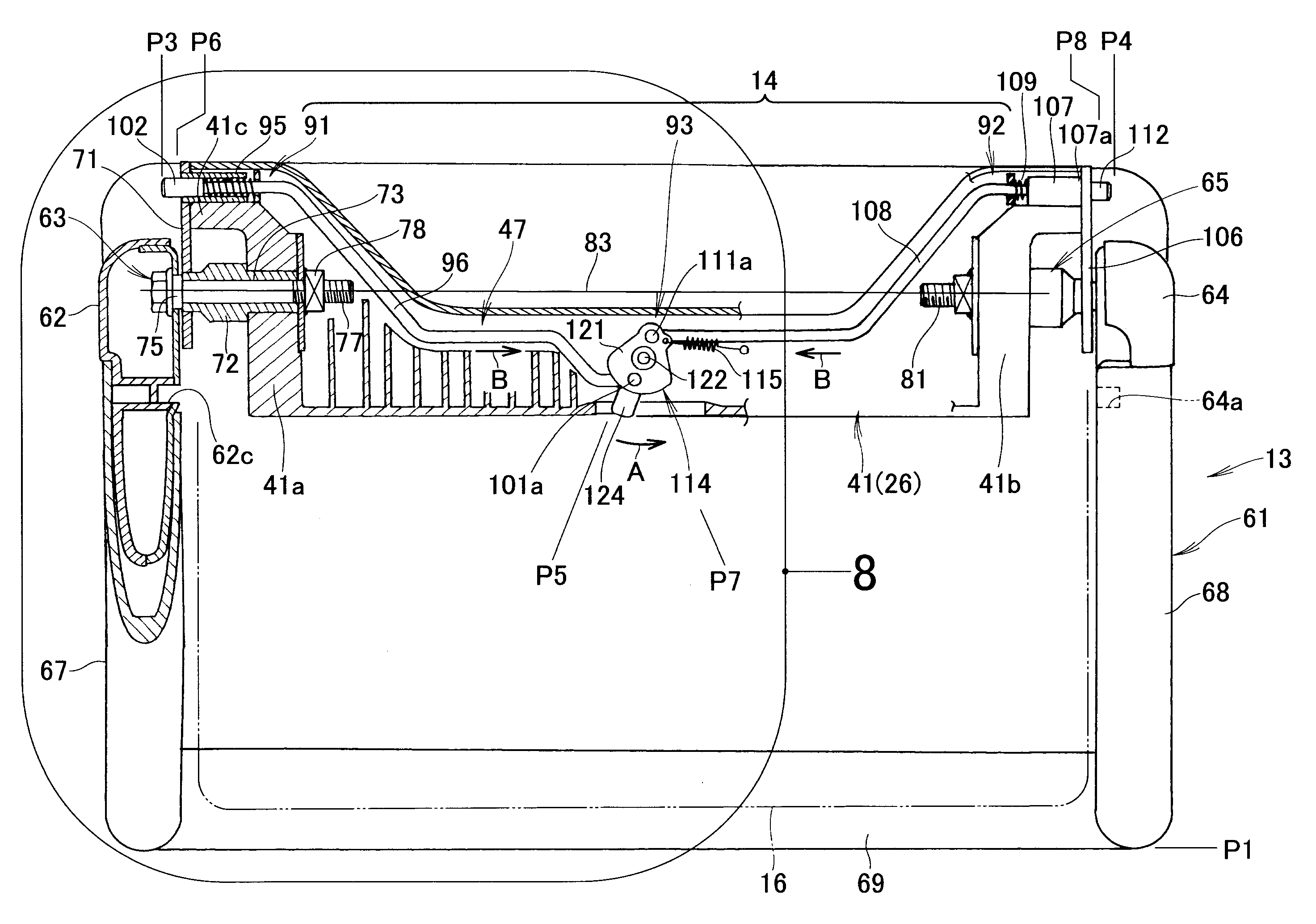
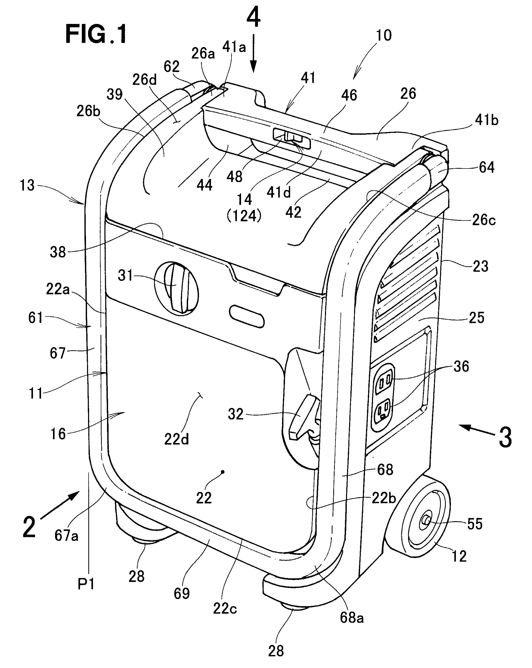
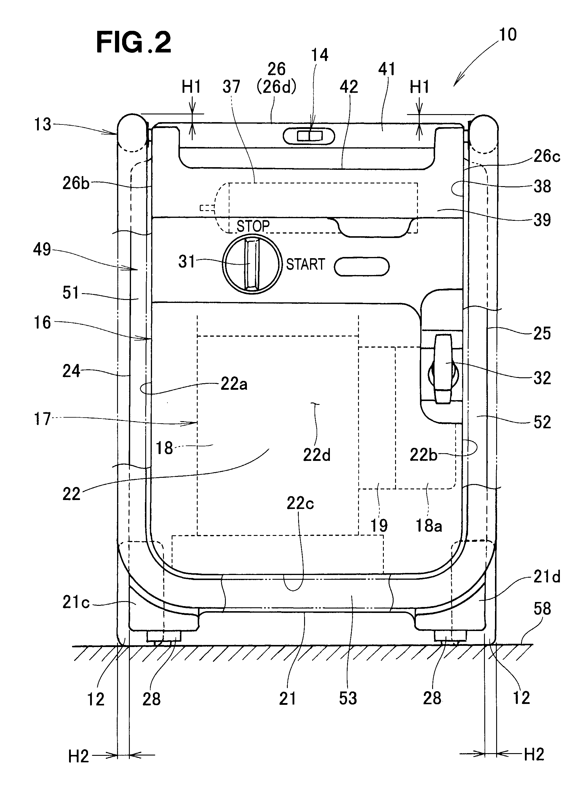
[0033]Reference is made initially to FIG. 1 showing in perspective a working machine equipped with a handle structure 13 (hereinafter referred to also as “working machine handle structure 13”) according to an embodiment of the present invention, and to FIG. 2 being a view taken in the direction of arrow 2 of FIG. 1. In the illustrated example of FIG. 1, the working machine 10 is a portable, towing-type power generator, which includes: a working machine body 11 having a substantially rectangular parallelepiped contour or shape; left and right wheels 12 (the left wheel 12 is shown in FIG. 2) rotatably mounted on the machine body 11; the working machine handle structure 13 pivotably mounted on the machine body 11; and a handle lock structure 14 (see also FIG. 6) for retaining the handle structure 13 in a locked state or position.

[0034]The working machine body 11 includes a case 16 formed in a substantially rectangular parallelepiped shape, and an engine / generator unit 17 provided withi...


PUM


Abstract

Handle lock structure includes: left and right lock members provided on a body of a working machine for movement into engagement with engaging portions of left and right handle sections of a handle as the handle is pivotally moved in a deploying direction from a stored position toward a deployed position, thereby locking the handle sections in the deployed position; and a lock cancellation lever for moving the left and right lock members out of the engagement with the engaging portions to compulsorily cancel the locking, by the left and right lock members, of the left and right handle sections in the deployed position.

Description

FIELD OF THE INVENTION[0001]The present invention relates to a handle lock structure for working machines in which a handle pivotally mounted on the body of a working machine is movable between a stored position where the handle is stored in the machine body and a deployed position where the handle is deployed from the machine body, and in which the machine body is towable by a user or human operator using the handle retained in the deployed position.BACKGROUND OF THE INVENTION[0002]Among the conventionally-known working machines are ones in which towing wheels are mounted on a bottom section of the body of the working machine (i.e., working machine body) and a pair of handle bars, constituting a towing handle, are pivotably mounted on a top section of the working machine body, an example of which is disclosed in Japanese Patent No. 4226404 (hereinafter referred to as “patent literature”). The pair of handle bars is pivotable between stored position where the handle is stored in the...

Claims


Application Information

Patent Timeline
Patent Type & Authority Patents(United States)
IPC IPC(8): A45C13/26
CPCB62B2205/20B62B1/00B62B5/067Y10T16/451Y10T16/44Y10T70/5774Y10T16/50
Inventor OKABE, KAKU
Owner HONDA MOTOR CO LTD
Why Eureka
Try Eureka