Spiral oven apparatus and method of cooking

a spiral oven and spiral oven technology, applied in the field of spiral ovens, can solve the problems of non-uniform flow, temperature and cooking conditions within the cooking chamber b, non-uniform cooking, significant differences in cooking uniformity and product appearance, etc., to achieve increased product throughput, reduced cooking times, and improved energy efficiency

Active Publication Date: 2014-02-11
MARLEN INT
View PDF60 Cites 22 Cited by
  • Summary
  • Abstract
  • Description
  • Claims
  • Application Information

AI Technical Summary

Benefits of technology

[0011]The present invention provides an improved spiral oven and a method of cooking which satisfy the needs and alleviate the problems discussed above. The advantages and benefits provided by the inventive spiral oven and cooking method include, but are not limited to: increased product throughput and reduced cooking times in the spiral oven; uniform flow and temperature of the cooking medium along the entire length of the spiral conveyor; uniform cooking rates and product appearances across the entire width of the spiral belt; the ability to impinge or otherwise apply the cooking medium directly onto the top, bottom or both the top and the bottom of the product as it is being conveyed over one, more than one, or all of the spiral flights; the ability to change or adjust the degree of impingement by varying the speed of the oven circulation fan and or changing delivery nozzles; greater energy efficiency and reduced generation of greenhouse gases; the creation of new spiral oven cooking methodologies which expand the use of spiral ovens to many additional food products and cooking applications and provide superior cooking results and performance.

Problems solved by technology

Heretofore, spiral ovens have had significant shortcomings which have significantly limited the types of cooking operations which can be performed in these ovens and have resulted in (a) significantly non-uniform flow, temperature, and cooking conditions within the cooking chamber 6 and (b) non-uniform cooking results which vary, for example, depending upon whether the food product is conveyed near the inside edge 28, near the outside edge 26, or on the central portion of the spiral conveyor belt 10.
This, in turn, can result in significant differences in cooking uniformity and product appearance.
The limited and non-uniform convective cooking flow circulation systems and patterns provided by the prior art spiral oven 2 also result in slower cooking times and reduced product throughput.
In addition, the available cooking applications for the prior art spiral oven 2 have also been further significantly restricted because the prior art spiral oven 2 is limited to the lateral convective flow of the cooking medium across the spiral flights 18 of the oven 2.
Spiral ovens 2 have thus not been able, for example, to provide the surface browning and texture benefits of an impingement-type oven which can impinge the hot cooking medium directly on the surface of the product at a much greater velocity.

Method used


Image

  • Spiral oven apparatus and method of cooking
  • Spiral oven apparatus and method of cooking
  • Spiral oven apparatus and method of cooking

Examples


Embodiment Construction

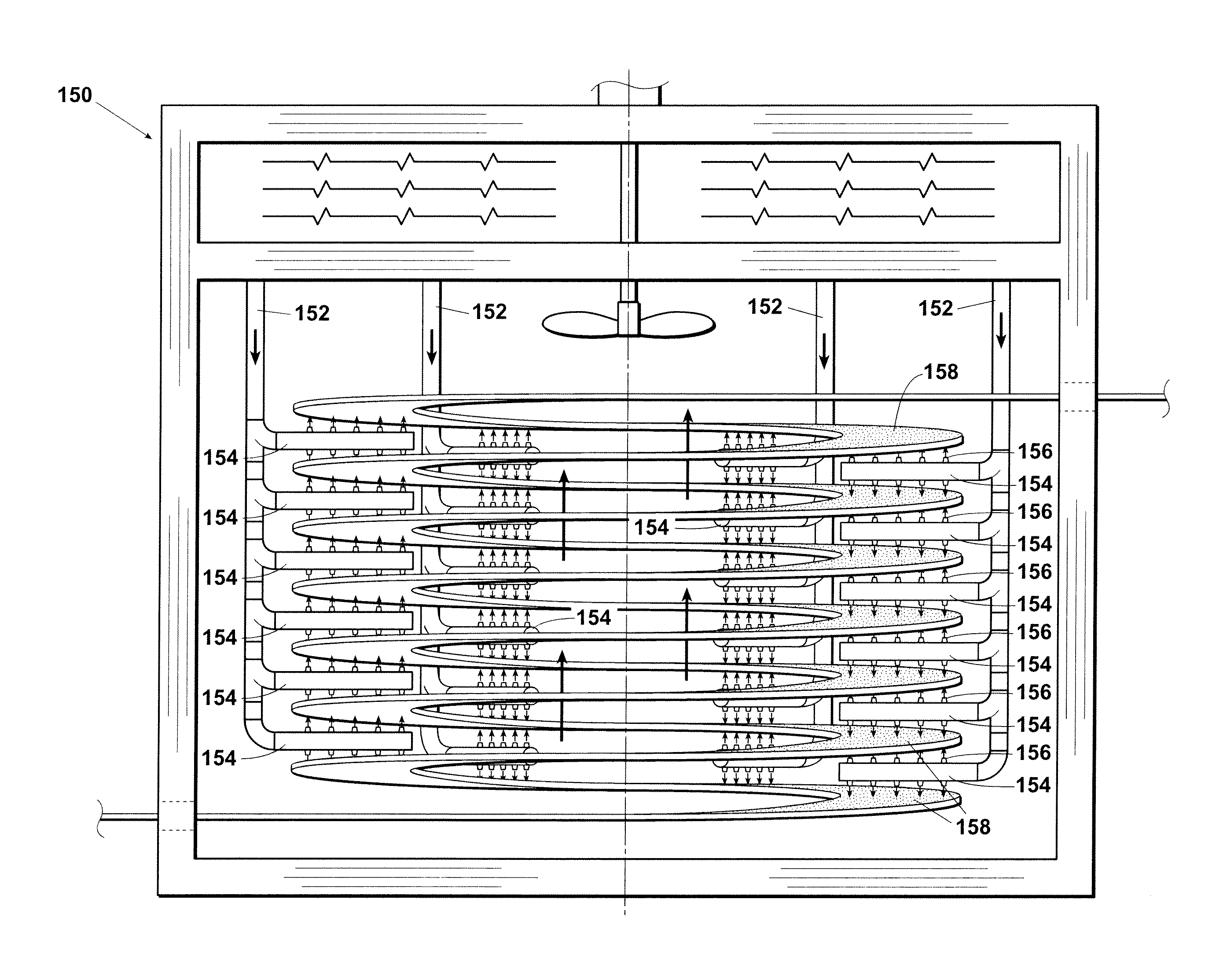
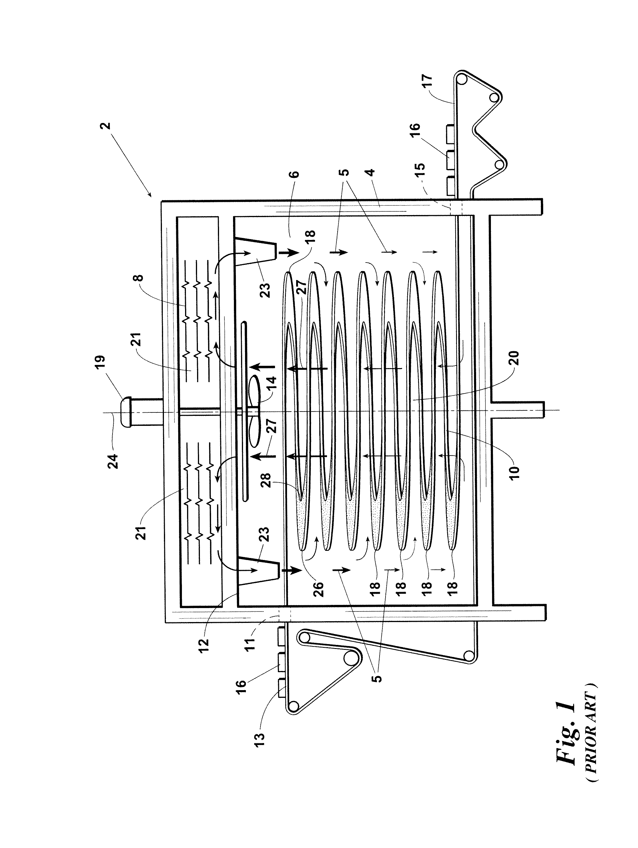
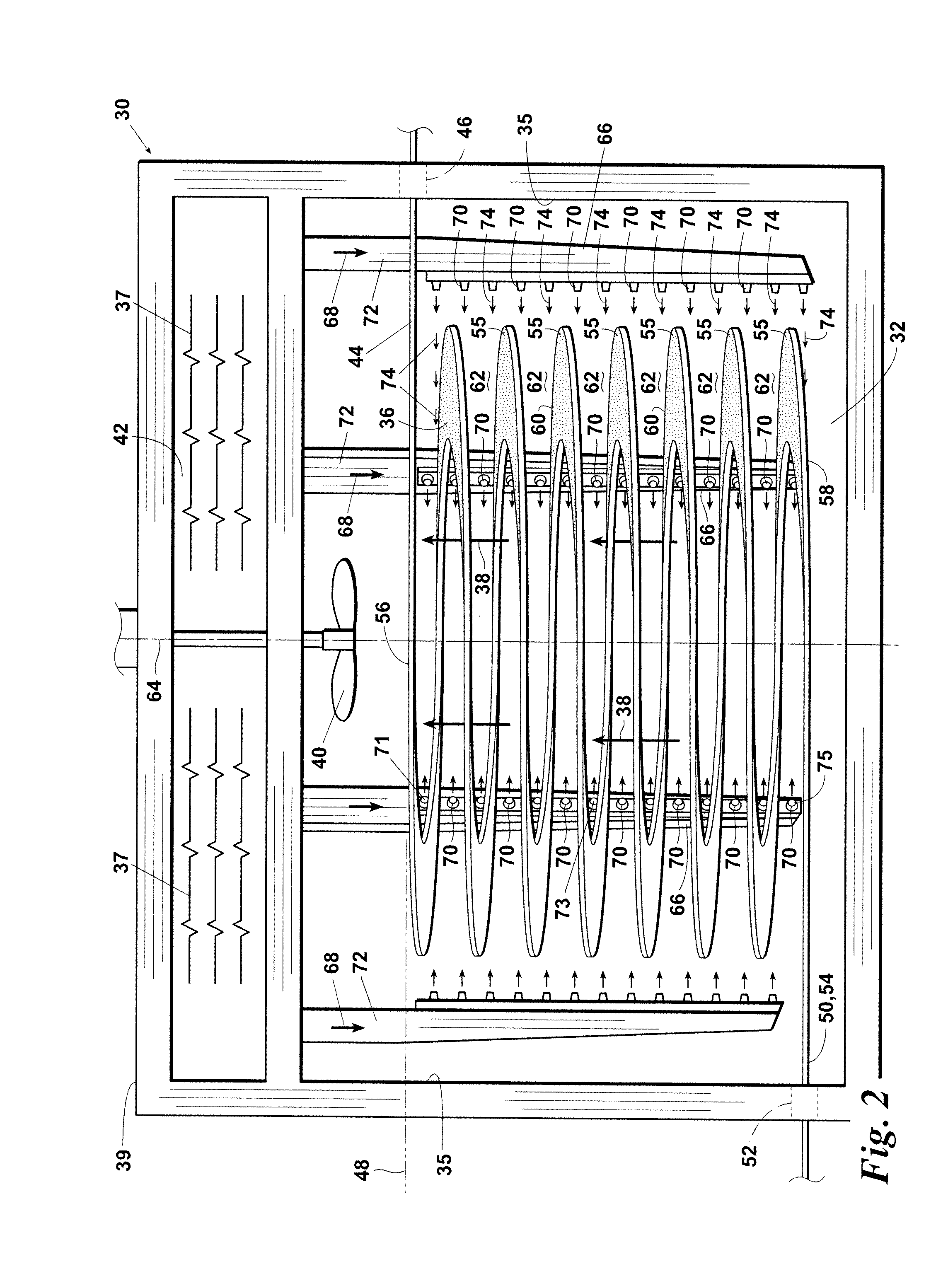
[0025]An embodiment 30 of the improved spiral oven provided by the present invention is illustrated in FIG. 2. As with the prior art oven 2, the inventive spiral oven 30 comprises: a cooking chamber 32 having an interior cooking chamber ceiling 34 and interior side walls 35; a spiral conveyor 36 within the interior of the cooking chamber 32 below the ceiling 34; a vertical cooking medium return flow path 38 surrounded by the spiral conveyor 36; and a circulation fan 40 located above the spiral conveyor 36 for drawing the cooking medium upwardly through the return flow path 38 and delivering the cooking medium through any desired type of heating element or system 37 in the upper heating chamber 42 and then into the cooking chamber 32.

[0026]Although the housing 39 of the inventive oven 30 includes both a cooking chamber 32 and an upper heating chamber 42, it will be understood that the term “cooking chamber,” as used herein and in the claims, refers to the area of the oven wherein the...


PUM


Abstract

A spiral oven and a method of cooking a food product in a spiral oven using a cooking medium wherein (a) the food product is conveyed within the oven cooking chamber by a spiral conveyor having a plurality of spiral flights and (b) the cooking medium is discharged either upwardly and / or downwardly within, or laterally into, one or more vertical gaps between adjacent pairs of spiral flights using one or more delivery duct structures which extend inside the interior of the cooking chamber.

Description

FIELD OF THE INVENTION[0001]The present invention relates to spiral ovens and to methods of cooking food products therein.BACKGROUND OF THE INVENTION[0002]A prior art spiral oven 2 used for cooking food products is schematically illustrated in FIG. 1. The prior art spiral oven 2 comprises: a housing 4 having a lower cooking chamber 6 and an upper circulation and heating chamber 8; a spiral conveyor belt 10 within the cooking chamber 6 for carrying the food product during the cooking process; an upper cooking chamber ceiling 12 which separates the cooking chamber 6 from the upper circulation and heating chamber 8; an upper side opening 11 in a sidewall of the cooking chamber 6 through which the upper end (typically an outfeed section) 13 of the conveyor 10 extends; a lower sidewall opening 15 through which the lower end (typically an infeed section) 17 of the spiral conveyor 10 extends; a circulation fan 14 for circulating a heating medium (e.g., air, combustion gas, steam, or a comb...

Claims


Application Information

Patent Timeline
Patent Type & Authority Patents(United States)
IPC IPC(8): A47J37/07A47J37/04A23L3/18
CPCA47J37/04A23L1/0128A21B1/48A47J37/07A23L3/18A23L5/15A23L5/13A23L5/17A21B1/245A47J37/043A47J37/044A47J37/045
Inventor HOWARD, DAVID
Owner MARLEN INT
Why Eureka
Try Eureka