
Digital pre-distortion power amplifying apparatus and method for digitally controlling synchronization thereof

a technology of power amplifier and digital pre-distortion, which is applied in the direction of digital transmission, gain control, transmission, etc., can solve problems such as distortion, and achieve the effect of preventing signal loss

Inactive Publication Date: 2014-02-11
ELECTRONICS & TELECOMM RES INST
View PDF8 Cites 21 Cited by
  • Summary
  • Abstract
  • Description
  • Claims
  • Application Information

AI Technical Summary

Benefits of technology

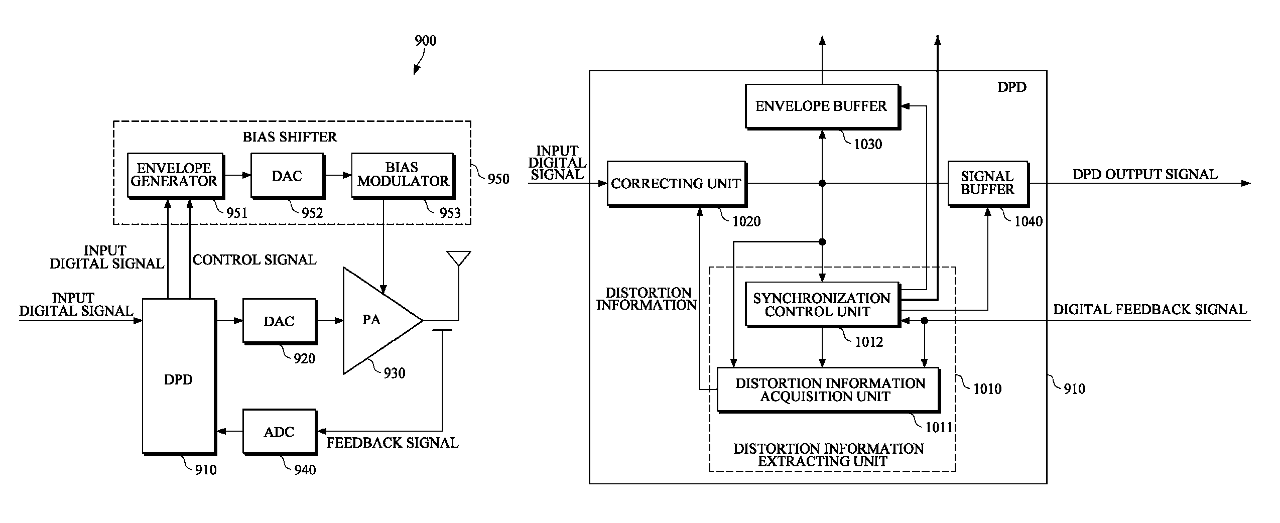
The patent is about a device and process to prevent signals from being lost due to inconsistent synchronization of an envelope tracking power amplifier. It also describes how to easily control the synchronization and reduce data distortion caused by the nonlinearity of the power amplifier.

Problems solved by technology

As described above, although the ET power amplifier is more advanced in efficiency than a fixed-bias-type power amplifier, there may be a problem that distortion may occur due to data loss when a power amplifier bias signal and an input RF signal of the power amplifier are not synchronized with each other.

Method used


Image

  • Digital pre-distortion power amplifying apparatus and method for digitally controlling synchronization thereof
  • Digital pre-distortion power amplifying apparatus and method for digitally controlling synchronization thereof
  • Digital pre-distortion power amplifying apparatus and method for digitally controlling synchronization thereof

Examples


Embodiment Construction

[0028]The following description is provided to assist the reader in gaining a comprehensive understanding of the methods, apparatuses, and / or systems described herein. Accordingly, various changes, modifications, and equivalents of the methods, apparatuses, and / or systems described herein will be suggested to those of ordinary skill in the art. Also, descriptions of well-known functions and constructions may be omitted for increased clarity and conciseness.

[0029]The present invention relates to an apparatus and method for achieving synchronization and preventing data distortion by applying a digital pre-distortion (DPD) technique to an envelope tracking (ET) power amplifier.

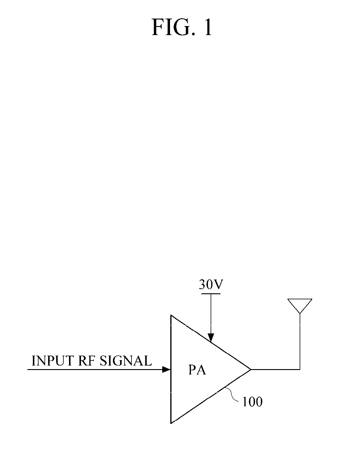
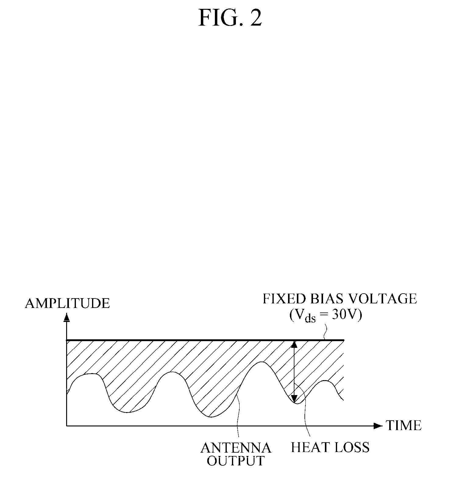
[0030]FIG. 1 is a diagram illustrating an example of a general power amplifier for use in a wireless system. Referring to FIG. 1, power amplifier 100 amplifies an input radio frequency (RF) signal according to a bias voltage and outputs the amplified RF signal through an antenna. In this case, regardless of the i...


PUM


Abstract

A digital pre-distortion (DPD) power amplifying apparatus and a method for digitally controlling synchronization of the DPD power amplifying apparatus, which includes a power amplifier, a bias shifter and a DPD unit, are provided. The method includes acquiring a DPD path delay time at a path along which an input signal is fed back to the DPD unit; delaying an input signal incoming to the power amplifier by the DPD path delay time and acquiring synchronization by delaying a bias signal a predetermined number of times until the bias signal and the delayed input signal are synchronized with each other; and in response to synchronization between the bias signal and the delayed input signal being established, pre-distorting the input signal according to a feedback signal output from the power amplifier.

Description

CROSS-REFERENCE TO RELATED APPLICATION(S)[0001]This application claims the benefit under 35 U.S.C. §119(a) of Korean Patent Application No. 10-2010-0131578, filed on Dec. 21, 2010, in the Korean Intellectual Property Office, the entire disclosure of which is incorporated herein by reference for all purposes.BACKGROUND[0002]1. Field[0003]The following description relates to a wireless communication system, and more particularly, to a power amplifier to amplify and output an output signal of a wireless communication system.[0004]2. Description of the Related Art[0005]A wireless communication system amplifies a radio-frequency (RF) signal using a power amplifier (PA) prior to transmission over an antenna and outputs the amplified RF signal.[0006]A power amplifier amplifies an incoming RF signal according to a bias voltage and outputs the amplified RF signal through an antenna. In amplifying an RF signal, to prevent heat loss due to a difference between a voltage of a signal output from...

Claims


Application Information

Patent Timeline
Patent Type & Authority Patents(United States)
IPC IPC(8): H03F1/26
CPCH03F3/24H04L27/368H03F1/0266H03F2200/102H03F1/3247
Inventor OH, JUNG-HOONKIM, JOON-HYUNGJO, GWEON-DOKIM, YOUNG-HOON
Owner ELECTRONICS & TELECOMM RES INST
Learn More