Radioisotope-powered energy source

a radioisotope and energy source technology, applied in radiation electrical energy, radiation applications, nuclear engineering, etc., can solve the problems of chemical battery size and load, sometimes associated with microelectronic devices, not always compatible with chemical batteries,

Inactive Publication Date: 2014-02-18
THE UNITED STATES OF AMERICA AS REPRESENTED BY THE SECRETARY OF THE NAVY
View PDF30 Cites 6 Cited by
  • Summary
  • Abstract
  • Description
  • Claims
  • Application Information

AI Technical Summary

Benefits of technology

[0005]Disclosed herein is a radioisotope-powered energy source comprising: a flexible center substrate, wherein the substrate comprises upper and lower surfaces which are both coated with the radioisotope or have a thin layer of the radioisotope bonded thereto; and two substantially identical sequences of layers bonded to each other and to the upper and lower surfaces via electrically insulating mesh barriers, wher

Problems solved by technology

While chemical batteries are very effective at providing the power needs of such devices, the size and durational requirements sometimes associated with microelectronic

Method used


Image

  • Radioisotope-powered energy source
  • Radioisotope-powered energy source
  • Radioisotope-powered energy source

Examples


Embodiment Construction

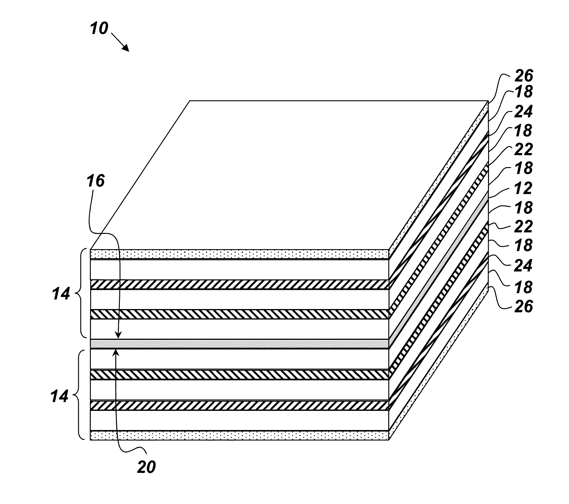
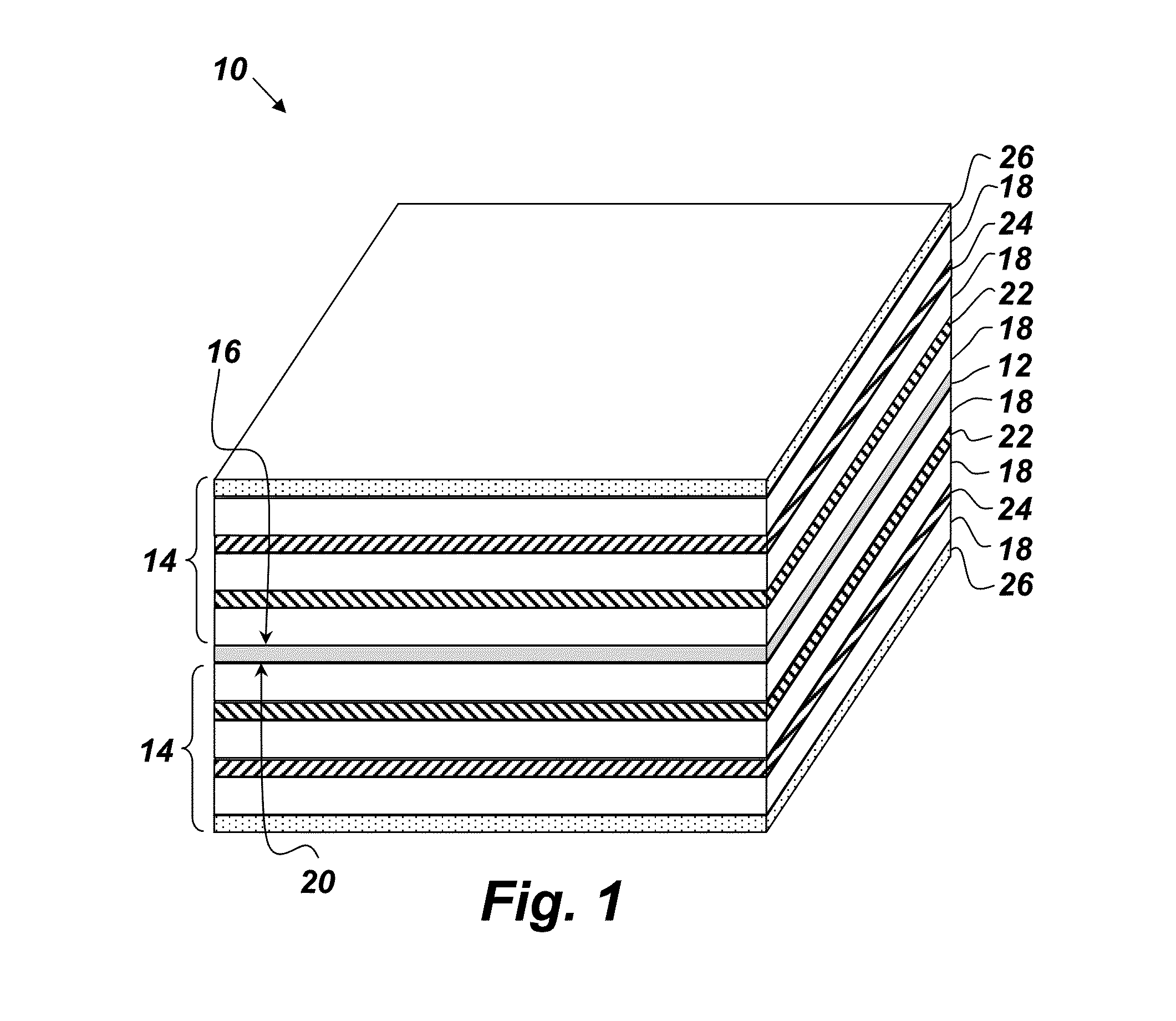
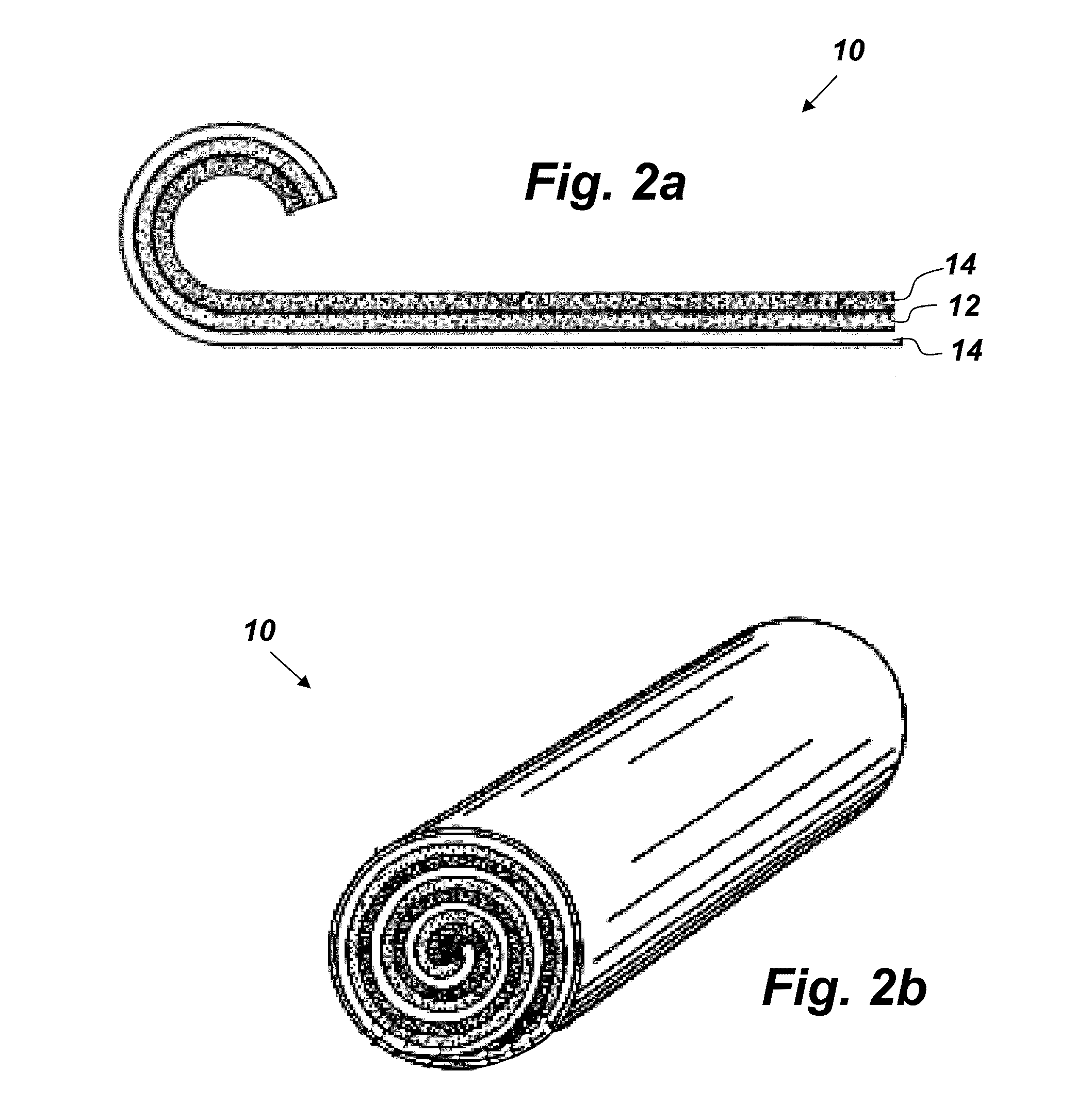
[0013]FIG. 1 depicts an embodiment of a radioisotope-powered energy source 10, which comprises a radioisotope-coated flexible center substrate 12, and two substantially identical sequences of layers 14. One sequence 14 is bonded to an upper surface 16 of the center substrate 12 via an electrically insulating mesh barrier 18. The other sequence 14 is bonded to a lower surface 20 via another electrically insulating mesh barrier 18. All of the constituent layers of each sequence 14 are also bonded to each other via electrically insulating mesh barriers 18. Each sequence 14 comprises the following layers bonded together in the following order: a first low-density alpha particle impact layer 22, a first high-density beta particle impact layer 24, and a photovoltaic layer 26.

[0014]The center substrate 12 may be made of any thin flexible material that is capable of carrying a layer of the radioisotope with minimal self-absorption of the emitted alpha particulates. A suitable example of the...


PUM


Abstract

A radioisotope-powered energy source comprising: a flexible center substrate coated with the radioisotope, wherein the substrate comprises upper and lower surfaces; and two substantially identical sequences of layers bonded to each other and to the upper and lower surfaces via electrically insulating mesh barriers, wherein each sequence comprises the following layers bonded together in a y-direction in the following order: a first low-density alpha particle impact layer, a first high-density beta particle impact layer, a second low-density alpha particle impact layer, a second radioisotope-coated substrate, a third low-density alpha particle impact layer, a second high-density beta particle impact layer, and a photovoltaic layer.

Description

FEDERALLY-SPONSORED RESEARCH AND DEVELOPMENT[0001]This invention is assigned to the United States Government and is available for licensing for commercial purposes. Licensing and technical inquiries may be directed to the Office of Research and Technical Applications, Space and Naval Warfare Systems Center, Pacific, Code 72120, San Diego, Calif., 92152; voice (619) 553-5118; ssc_pac_t2@navy.mil. Reference Navy Case Number 100794.BACKGROUND OF THE INVENTION[0002]The present invention relates to self-contained power cells capable of supplying electrical energy, and more particularly to a compact energy source capable of supplying a low level of energy for a relatively long period of time.[0003]Electric power cells provide self-contained sources of electrical energy for driving external loads. Chemical batteries are a common example of a practical electric power cells, in that they are relatively inexpensive to produce and capable of supplying a reasonably high energy output, even thou...

Claims


Application Information

Patent Timeline
IPC IPC(8): G21H1/00G21H1/02
CPCG21H1/02G21H1/06G21H1/04
Inventor BAUMBAUGH, JOEL, T.
Owner THE UNITED STATES OF AMERICA AS REPRESENTED BY THE SECRETARY OF THE NAVY
Why Eureka
Try Eureka