Radio communication base station apparatus and pilot transmitting method

a radio communication and base station technology, applied in the direction of broadcasting with distribution, transmission path division, wireless commuication services, etc., can solve the problems of transmission performance degradation, delay wave due to multi-path cannot be avoided, etc., and achieve the effect of improving the accuracy of channel estimation value interpolation

Active Publication Date: 2014-02-18
PANASONIC INTELLECTUAL PROPERTY CORP OF AMERICA
View PDF18 Cites 19 Cited by
  • Summary
  • Abstract
  • Description
  • Claims
  • Application Information

AI Technical Summary

Benefits of technology

[0015]According to the present invention, it is possible to improve the accuracy of interpolation for channel estimation values between subframes.

Problems solved by technology

However, when high-speed transmission is performed in mobile communication, the influence of delay waves due to multi-path cannot be avoided, and transmission performances degrade due to frequency selective fading.

Method used


Image

  • Radio communication base station apparatus and pilot transmitting method
  • Radio communication base station apparatus and pilot transmitting method
  • Radio communication base station apparatus and pilot transmitting method

Examples


embodiment 1

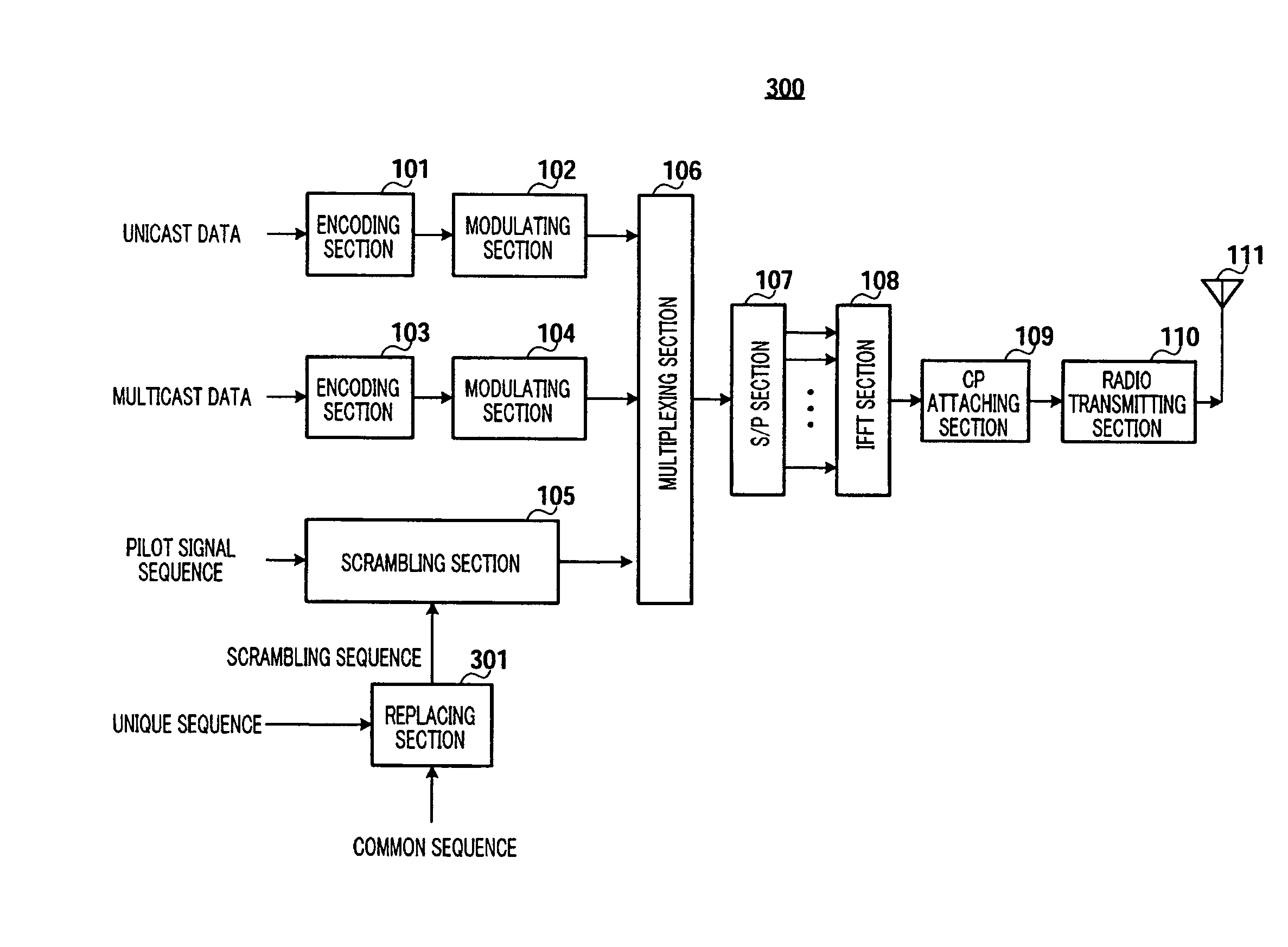
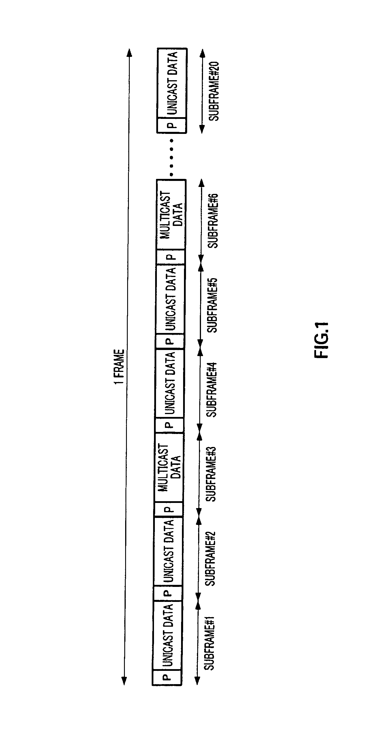
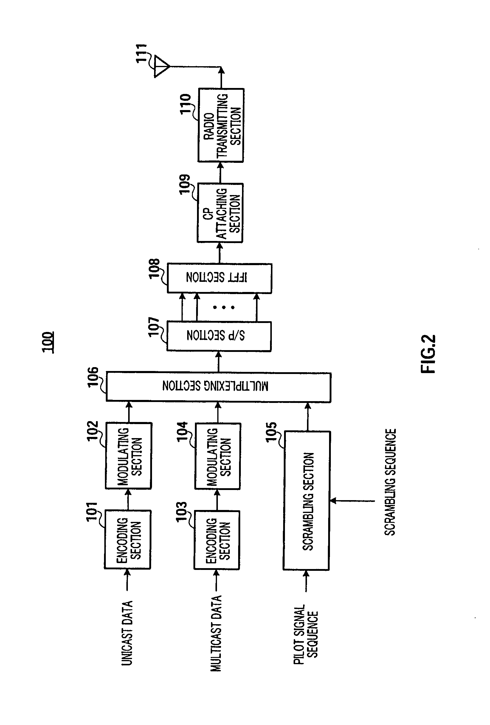
[0040]The base station according to the present embodiment is used in a radio communication system. In this radio communication system, subframes which a plurality of base stations use to transmit mutually different data and subframes which a plurality of base stations use to transmit mutually same data, are time-multiplexed. In particular, the base station according to the present embodiment is adequate for a radio communication system where subframes for unicast data (hereinafter “unicast subframes”) and subframes for multicast data (hereinafter “multicast subframes”) are time-multiplexed, as shown in above-described FIG. 1. Therefore, in the following explanations, as an example, unicast subframes are used as the subframes which a plurality of base stations use to transmit mutually different data, and multicast subframes are used as the subframes which a plurality of base stations use to transmit the same data. Further, the frame structure according to the present embodiment is t...

embodiment 2

[0088]According to Embodiment 1, channel estimation value gi calculated when a channel estimation is performed for multicast data, is a channel estimation value comprised of channel estimation value hi for cell A and channel estimation value li for cell B, and, consequently, this calculated channel estimation value cannot be used for channel estimation for unicast data.

[0089]Therefore, with the present embodiment, out of the unique sequence and the common sequence included in the scrambling sequence, a phase rotation that is unique to a base station and that differs between cells is applied to the common sequence.

[0090]FIG. 16 illustrates the configuration of base station 500 according to the present embodiment. Base station 500 employs a configuration having phase rotating sections 501 and 502 in addition to the configuration shown in Embodiment 1 (FIG. 2). Here, in FIG. 16, the same components as in FIG. 2 will be assigned the same reference numerals and detail explanations thereo...

embodiment 3

[0099]A case will be explained below with the present embodiment where different multicast data is transmitted per cell group comprised of a plurality of cells. According to the present embodiment, for example, as shown in FIG. 18, in a case where cells A to G form cell group 1 and cells H to N form cell group 2, while multicast data 1 is transmitted in cells A to G of cell group 1, multicast data 2, which is different from multicast data 1, is transmitted in cells H to N of cell group 2.

[0100]In this case, if pilots for multicast subframes are mapped in the same positions in all cells, the accuracy of channel estimation for multicast data is assumed to degrade in cells nearby the cell group boundary (cells A, B, M and N in FIG. 18). For example, the accuracy of channel estimation for multicast data 1 is assumed to degrade in cells A and B in cell group 1, and, further, the accuracy of channel estimation for multicast data 2 is assumed to degrade in cells M and N in cell group 2. Th...


PUM


Abstract

A base station realizing enhancement of the interpolation accuracy of the channel estimate between sub-frames. In a base station (100), a scrambling section (105) carries out scrambling such that a predetermined pilot signal sequence is multiplied by a scrambling sequence containing both a sequence unique to the base station (100) and different with cells and a sequence common to base stations for each chip and generates a pilot sequence containing both a pilot for unicast sub-frame and a pilot for multicast sub-frame, a multiplexing section (106) for time-multiplexing the pilot sequence, the unicast data symbol, and a multicast data symbol for each sub-frame, and an S / P section (107) converts the pilot sequences, the unicast data symbols, and the multicast data symbols sequential serially inputted from the multiplexing section (106) the numbers of which are equal to the number of subcarries included in one OFDM symbol into parallel ones and outputs them to an IFFT section (108).

Description

TECHNICAL FIELD[0001]The present invention relates to a radio communication base station apparatus and a pilot transmission method.BACKGROUND ART[0002]Recently, in mobile communications, various information such as image and data in addition to audio are targets for information transmission. With this trend, demands for high-reliable, high-speed transmission are increased. However, when high-speed transmission is performed in mobile communication, the influence of delay waves due to multi-path cannot be avoided, and transmission performances degrade due to frequency selective fading.[0003]As a technique for avoiding frequency selective fading, multicarrier communication represented by the OFDM (Orthogonal Frequency Division Multiplexing) scheme has attracted attention. The multicarrier communication is a technique of performing high-speed transmission by transmitting data using a plurality of subcarriers where the level of transmission speed is suppressed not to cause frequency sele...

Claims


Application Information

Patent Timeline
Patent Type & Authority Patents(United States)
IPC IPC(8): H04W88/08
CPCH04L27/2613H04L5/0048H04L25/0232H04L5/0007H04L27/26134
Inventor FUKUOKA, MASARUNISHIO, AKIHIKOMINAMIDA, NORIAKI
Owner PANASONIC INTELLECTUAL PROPERTY CORP OF AMERICA
Why Eureka
Try Eureka