Fuel injection control device

a control device and fuel injection technology, applied in mechanical equipment, machines/engines, electric control of exhaust gases, etc., can solve problems such as prolonged dead time, and achieve the effect of widening the injection amount range and the lower limit range of injection amoun

Active Publication Date: 2014-02-25
ISUZU MOTORS LTD
View PDF9 Cites 0 Cited by
  • Summary
  • Abstract
  • Description
  • Claims
  • Application Information

AI Technical Summary

Benefits of technology

[0006]When using the above-described injector for low-pressure injection as a means for injecting fuel into an exhaust passage, the atmosphere pressure inside the exhaust passage (outside the cylinder) is lower than inside the combustion chamber (inside the cylinder). As a result, the set pressure of the needle valve can be made lower than is the case when the injector is used for in-cylinder injection, and it becomes possible also to use a driving driver without fuel pressurization. Therefore, using the above-described injector for low-pressure injection as a means for injecting fuel into an exhaust passage allows reducing costs, by omitting a pressurization circuit that raises the pressure of fuel that is fed to the injector.
[0008]Therefore, it is an object of the present invention to provide a fuel injection control device that affords a wider lower limit range of injection amount by a injector for cylinder outside injection, and that can respond to injection requirements over a wider injection amount range.
[0010]The present invention affords the advantageous effect of providing a fuel injection control device that affords a wider lower limit range of injection amount by a injector for cylinder outside injection, and that can respond to injection requirements over a wider injection amount range.

Problems solved by technology

However, omitting the pressurization circuit tends to result in a protracted dead time owing to the resulting drop in driving torque.

Method used


Image

  • Fuel injection control device
  • Fuel injection control device
  • Fuel injection control device

Examples


Embodiment Construction

[0016]A preferred embodiment of the present invention is explained in detail below with reference to accompanying drawings.

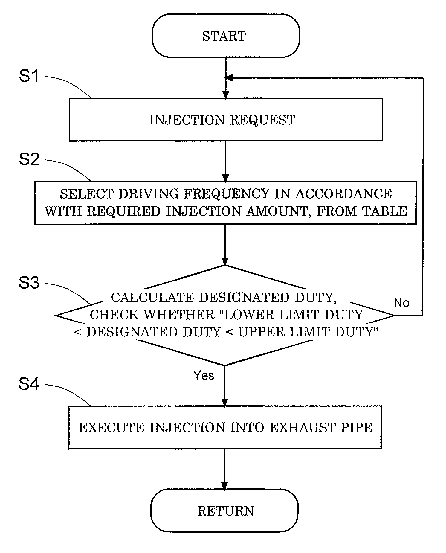
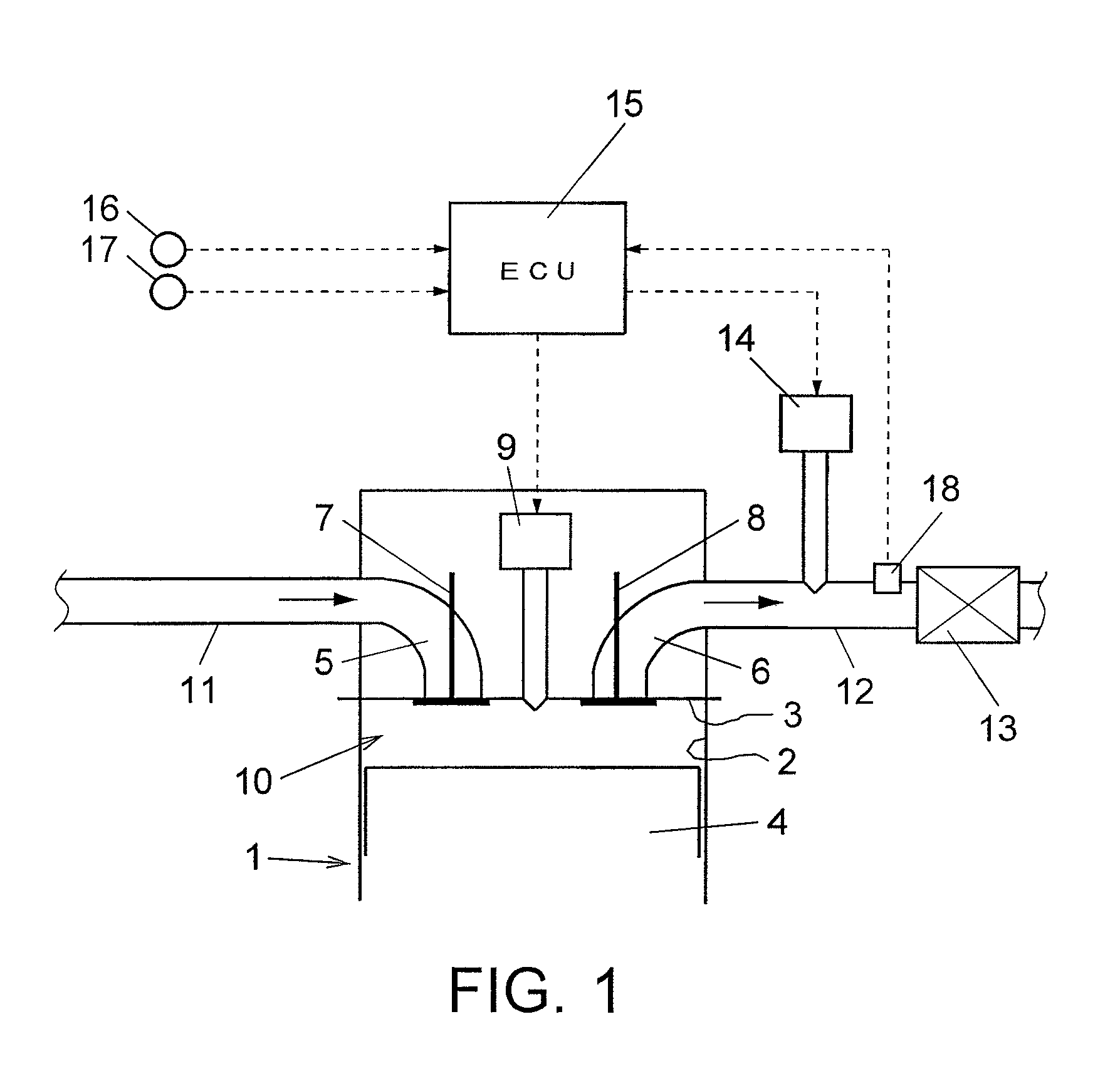
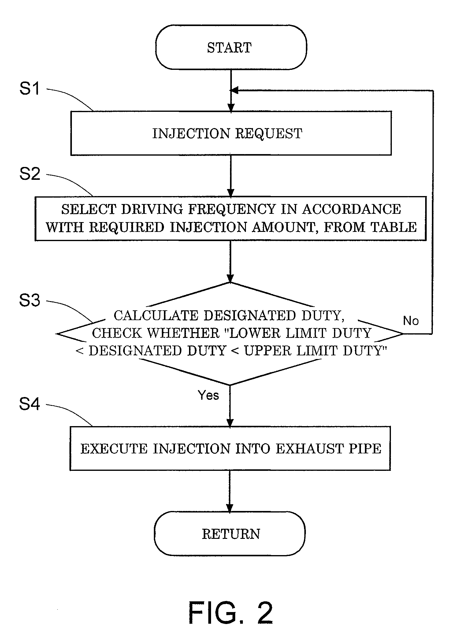
[0017]As illustrated in FIG. 1, an engine 1 (in the present embodiment, a diesel engine) comprises, for instance, a cylinder 2, a cylinder head 3, a piston 4, an intake port 5, an exhaust port 6, an intake valve 7, an exhaust valve 8 and an in-cylinder injector (injector for cylinder inside injection) 9. A combustion chamber 10 is formed in the space delimited by the cylinder 2, the cylinder head 3 and the piston 4. Fuel is injected directly from the in-cylinder injector 9 into the combustion chamber 10. An intake passage (intake pipe) 11 is connected to the intake port 5. An exhaust passage (exhaust pipe) 12 is connected to the exhaust port 6.

[0018]The fuel injection control device according to the present embodiment is used as an exhaust purification device of the engine.

[0019]Such a fuel injection control device comprises a filter (diesel particulate filter) ...


PUM


Abstract

Provided is a fuel injection control device that affords a wider lower limit range of injection amount by a injector for cylinder outside injection, and that can respond to injection requirements over a wider injection amount range. A fuel injection control device includes: a injector 14 for cylinder outside injection that injects fuel into an exhaust passage 12 of an engine 1, in an amount corresponding to a duty ratio; and a control means 15 for controlling the injector 14 for cylinder outside injection, wherein the control means 15 changes an injector driving frequency upon determining the duty ratio, such that the frequency is lowered, stepwise or continuously, as the required injection amount decreases.

Description

CROSS REFERENCE TO RELATED APPLICATIONS[0001]This application is entitled to the benefit of and incorporates by reference essential subject matter disclosed in International Patent Application No. PCT / JP2009 / 052671 filed on Feb. 17, 2009 and Japanese Patent Application No. 2008-037455 filed Feb. 19, 2008.TECHNICAL FIELD[0002]The present invention relates to a fuel injection control device provided with a injector for cylinder outside injection that injects fuel into an exhaust passage of an engine.BACKGROUND ART[0003]The exhaust gas discharged by a diesel engine contains, for instance, particulate matter (PM) and nitrogen oxides (NOx). There are methods in which a filter (diesel particulate filter) having a catalyst or the like is provided in an exhaust passage of an engine, in order to capture PM in the exhaust gas, and fuel is injected into the exhaust passage, upstream of the filter, in order to remove the PM captured by the filter (see Japanese Patent Application Laid-open No. 2...

Claims


Application Information

Patent Timeline
Patent Type & Authority Patents(United States)
IPC IPC(8): F01N3/18
CPCF01N2900/1806F01N2610/146Y02T10/47F01N3/0253F01N2560/08F01N3/035F01N9/002F01N2560/06F01N3/36F01N2610/03Y02T10/40
Inventor NAGAOKA, DAIJINAKADA, TERUOOOGUSHI, AKIHIDEYUZA, HIROYUKI
Owner ISUZU MOTORS LTD
Why Eureka
Try Eureka