
Interfacial refraction accommodating lens (IRAL)

a technology of iral and refraction, applied in the field of intraocular lenses, can solve the problems of fixed refractive power, inability to change the focus in response to changing patient's focal distance needs, and varying degrees of vision impairmen

Active Publication Date: 2014-02-25
HOYA CORP
View PDF2 Cites 26 Cited by
  • Summary
  • Abstract
  • Description
  • Claims
  • Application Information

AI Technical Summary

Benefits of technology

The present invention is a lens assembly that can accommodate a wide range of refractive power, including the natural eye and potentially more in case of other eye diseases such as age-related macular degeneration. It offers a simple and inexpensive construction and can be implanted using existing surgical instruments and techniques. The lens assembly is designed to mimic conventional monofocal IOLs and does not require special surgical skills or training. The lens assembly can include a variety of fluids or liquids that are immiscible and separated by an optically acceptable membrane or film to prevent mixing. The assembly provides a means for varying its sensitivity to the force applied by the capsular unit. Overall, the invention provides a versatile and effective lens assembly for refractive correction.

Problems solved by technology

Cataracts occur when the natural lens of the eye or of its surrounding transparent membrane becomes clouded and obstructs the passage of light resulting in varying degrees of vision impairment.
Such conventional IOLs, however, have the drawback that they have a fixed refractive power and are therefore unable to change their focus in response to changing focal distance needs of the patient, such as reading, or working on a computer.
One disadvantage of this approach is that a fluid source, a fluid pump and a flow control valve all must be provided within close proximity to the lens.
One principal disadvantage of this type of system is the relatively large amount of energy that is required to polarize the liquid crystal material, on the order of 25 volts.
This does not only require a relatively larger force but also fails to deliver larger changes in diopter due to the lack of space in the anterior chamber.
The above described and other prior attempts to provide an intraocular lens with variable accommodation are generally complex systems.
These complex systems are costly and difficult to manufacture and often times impractical to implement in the eye of a human.
In addition, multifocal IOLs provide a limited number of distances at which vision is adequate.

Method used


Image

  • Interfacial refraction accommodating lens (IRAL)
  • Interfacial refraction accommodating lens (IRAL)
  • Interfacial refraction accommodating lens (IRAL)

Examples


Embodiment Construction

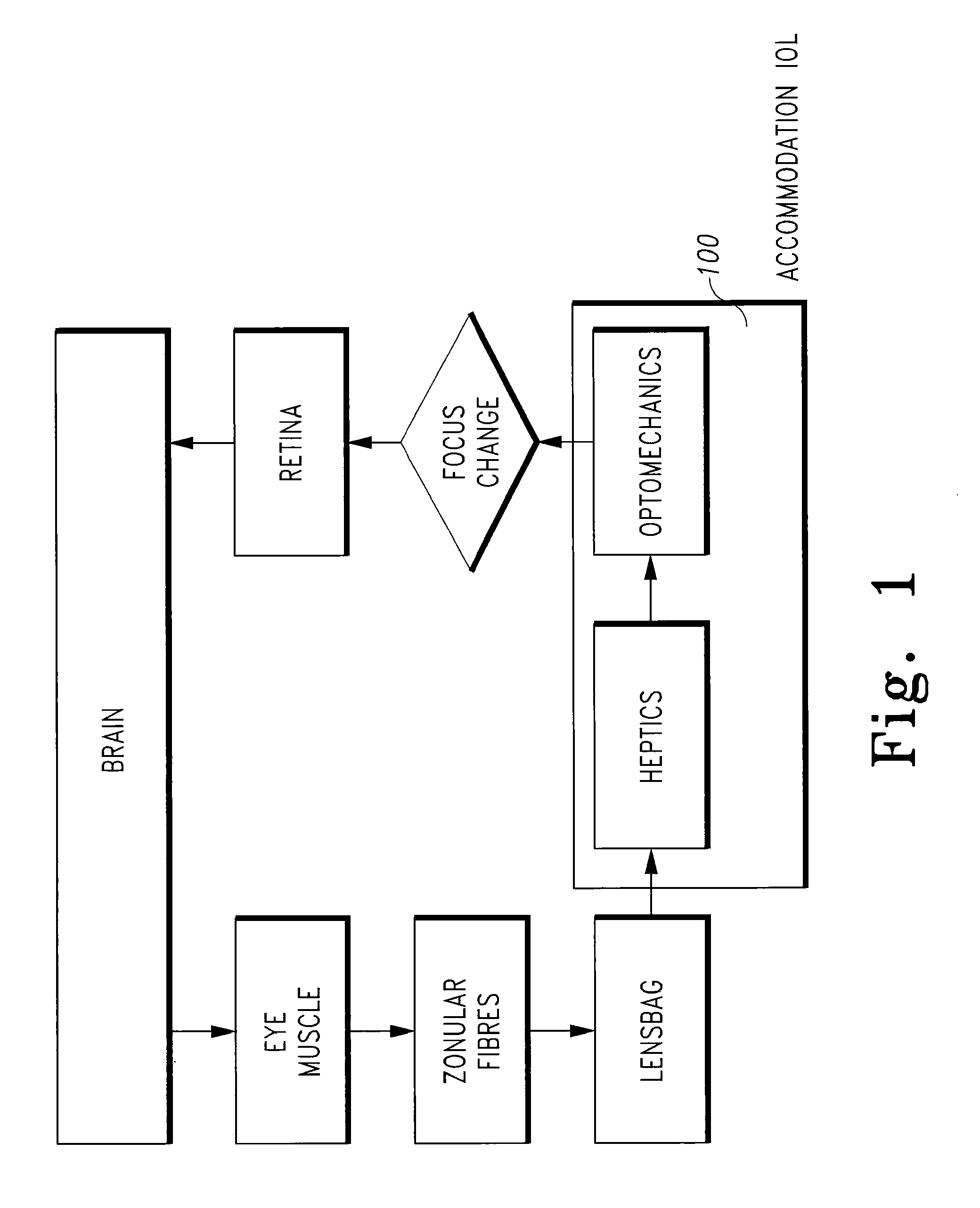
[0051]The basic principles of accommodating lenses are, of course, well known to one skilled in the art. These principles are illustrated at FIGS. 1 and 2 (and associated disclosure at column 4 line 20 through line 52) of U.S. Pat. No. 5,489,302 that disclosure being specifically incorporated by reference herein.

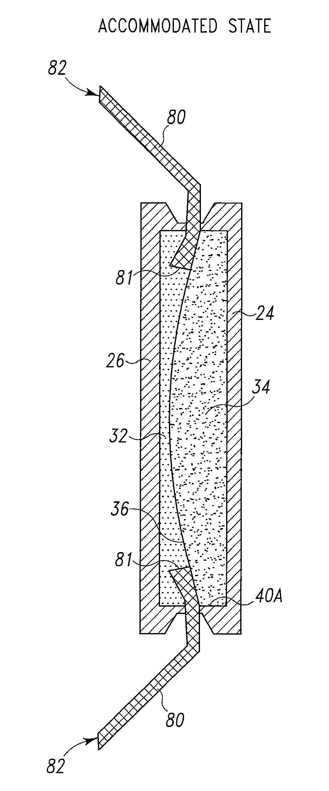
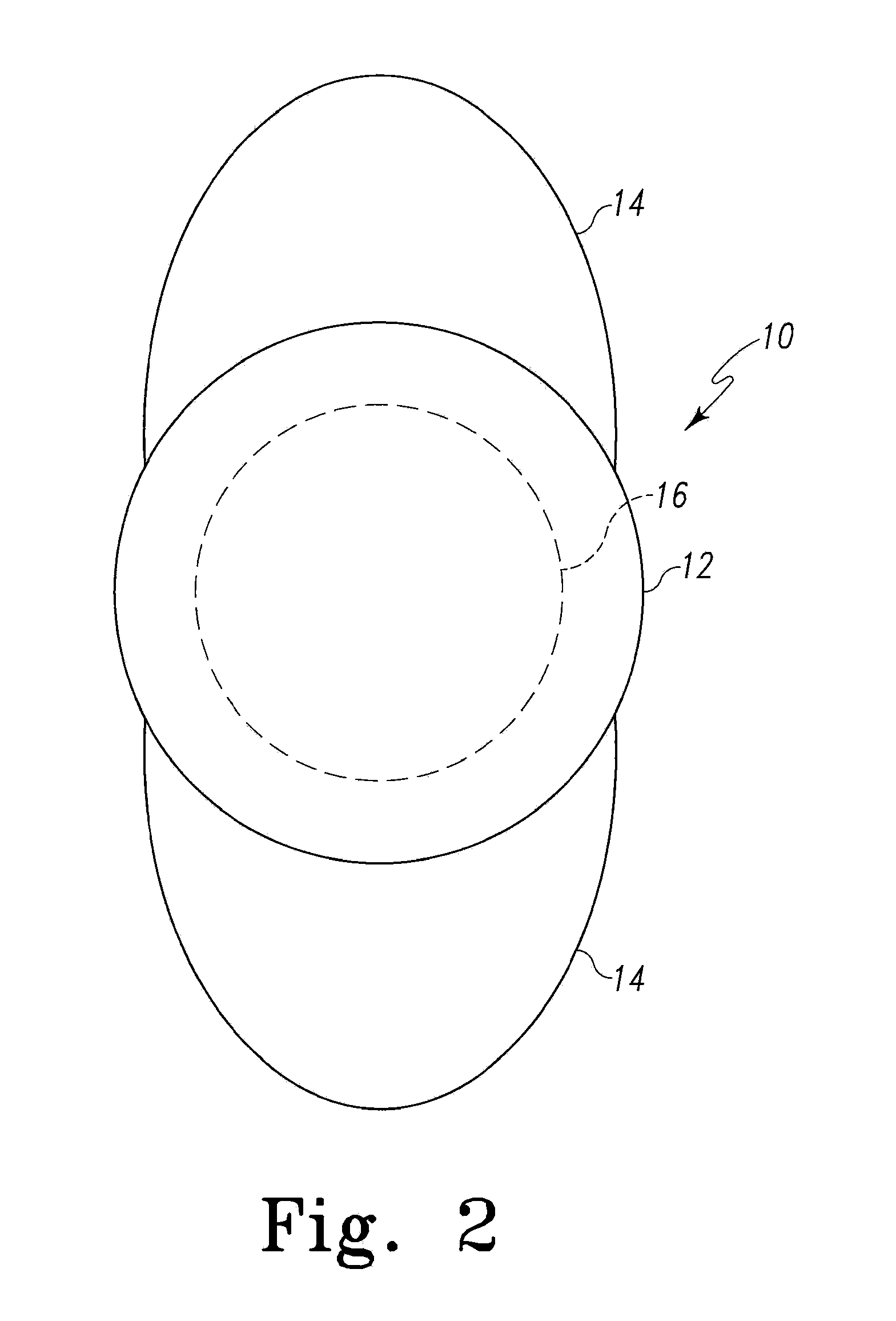
[0052]Generally, in one aspect, this invention is an implantable interfacial refraction ophthalmic lens (IRAL) assembly or apparatus which adjusts its focal distance in response to changing physiologic needs of the user of said lens (e.g., a patent in which the lens has been implanted.). The lens comprises a flexible optic chamber, lens body, or optic and cooperating haptics. The optic chamber is defined by opposed, substantially parallel, visually transparent, generally circular, elastic or stretchable discs or walls, which are flexibly coupled at their edges and spaced apart to define a closed fluidic chamber. The fluidic chamber includes first and second liquids, the liqu...


PUM


Abstract

This invention relates to intraocular lenses. More particularly, this invention relates to intraocular lenses that have the ability to alter the light refractive power in response to changes in the tension of the ciliary muscle or ciliary body of the eye or any other accommodative forces. Lenses of this invention are generally referred to as interfacial, i.e., lens properties being defined as the interface of two liquids having different refractive indices, refractive accommodating lenses (IRAL).

Description

CROSS REFERENCE TO RELATED APPLICATIONS[0001]This application is a U.S. national stage application filed under 35 U.S.C. 371 from PCT international application number PCT / US 2010 / 024518 filed on Feb. 18, 2010, which claims benefit of U.S. application Ser. No. 12 / 388,254 filed on Feb. 18, 2009 (now U.S. Pat No. 8,034,106).FIELD OF THE INVENTION[0002]This invention relates to intraocular lenses. More particularly, this invention relates to intraocular lenses that have the ability to alter the light refractive power in response to changes in the tension of the ciliary muscle or ciliary body of the eye or any other accommodative forces. Lenses of this invention are generally referred to as accommodating lenses.BACKGROUND OF THE INVENTION[0003]The natural lens of a human eye is a transparent crystalline body, which is contained within a capsular bag located behind the iris and in front of the vitreous cavity in a region known as the posterior chamber. The capsular bag is attached on all ...

Claims


Application Information

Patent Timeline
Patent Type & Authority Patents(United States)
IPC IPC(8): A61F2/16
CPCA61F2/1635A61F2250/0053A61F2002/1682
Inventor MENTAK, KHALIDSTEINACHER, BEDASTUCKLIN, PHILIPPFLUCKIGER, HANS
Owner HOYA CORP
Learn More