
Imaging forming apparatus

a technology forming chamber, which is applied in the direction of electrographic process apparatus, corona discharge, instruments, etc., can solve the problems of excessive equipment, increased cost increased electric energy consumption of image forming apparatus, etc., and achieves the effect of convenient mounting and demounting

Inactive Publication Date: 2014-02-25
CANON KK
View PDF7 Cites 3 Cited by
  • Summary
  • Abstract
  • Description
  • Claims
  • Application Information

AI Technical Summary

Benefits of technology

[0010]In Japanese Laid-open Patent Application Sho 58-217982 and Japanese Laid-open Patent Application Hei 9-138629, the cooler and the compressor are standard, equipment of the main assembly of the apparatus. Therefore, the cost of the image forming apparatus increases, and the electric energy consumption thereof also increases.
[0012]Accordingly, it is a principal object of the present invention to provide an image forming apparatus, in which a cooling device can be easily mounted and demounted, so that the inside of the main assembly of the apparatus can be effectively cooled depending on the desire, substantially without changing the air flow inside the main assembly of the apparatus.

Problems solved by technology

However, the conventional structures involve the following problems.
Therefore, the cost of the image forming apparatus increases, and the electric energy consumption thereof also increases.
Therefore, the image forming apparatus may have excessive equipment, depending on the users.

Method used


Image

  • Imaging forming apparatus
  • Imaging forming apparatus
  • Imaging forming apparatus

Examples


embodiment 1

1. General Arrangement and Operation of Image Forming Apparatus:

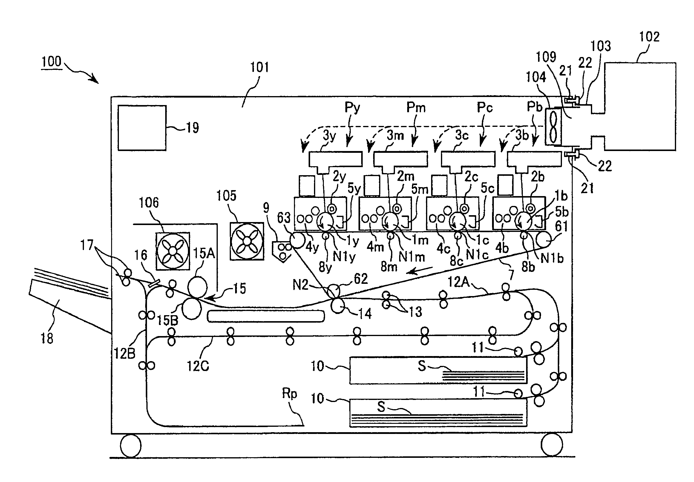
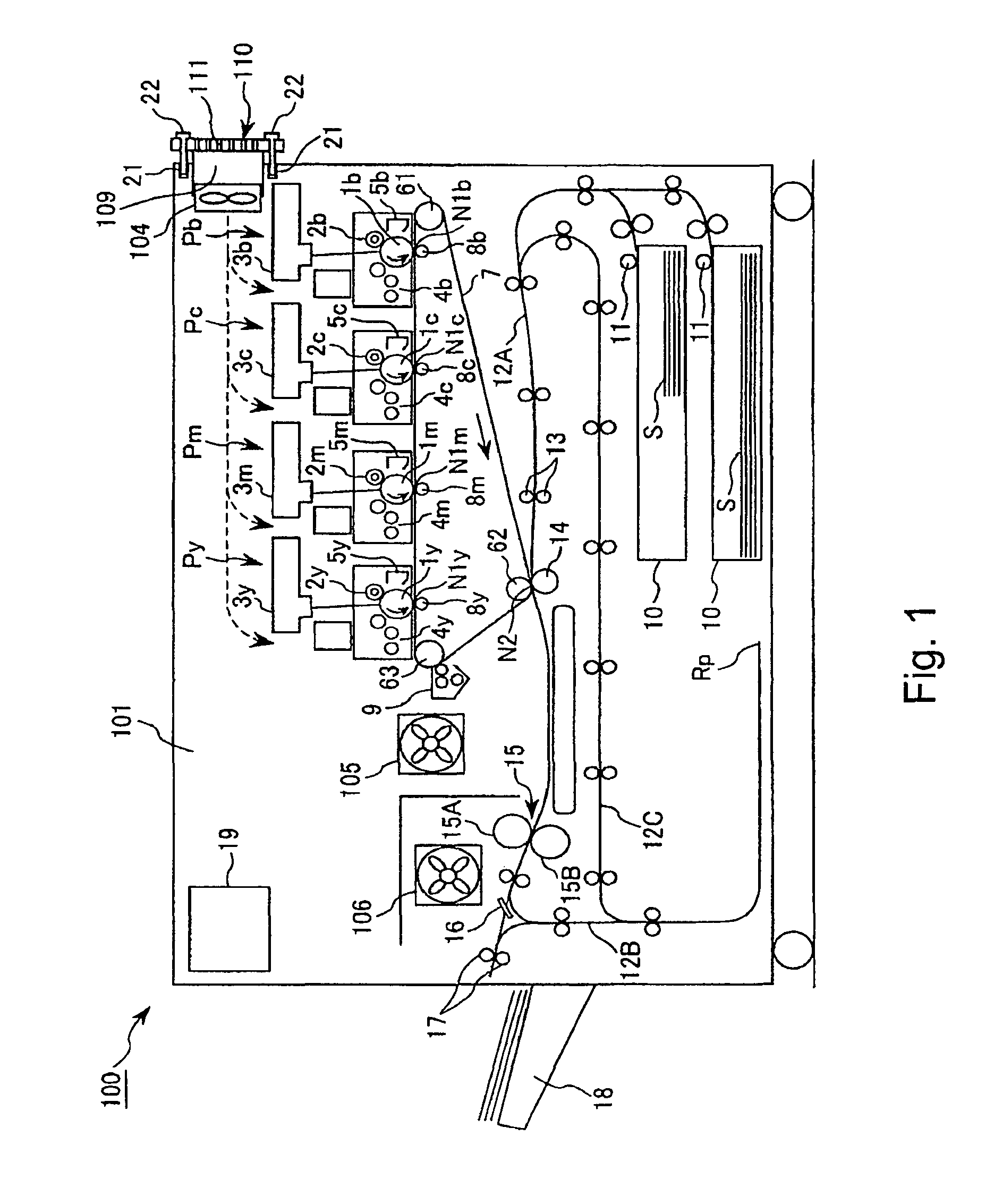
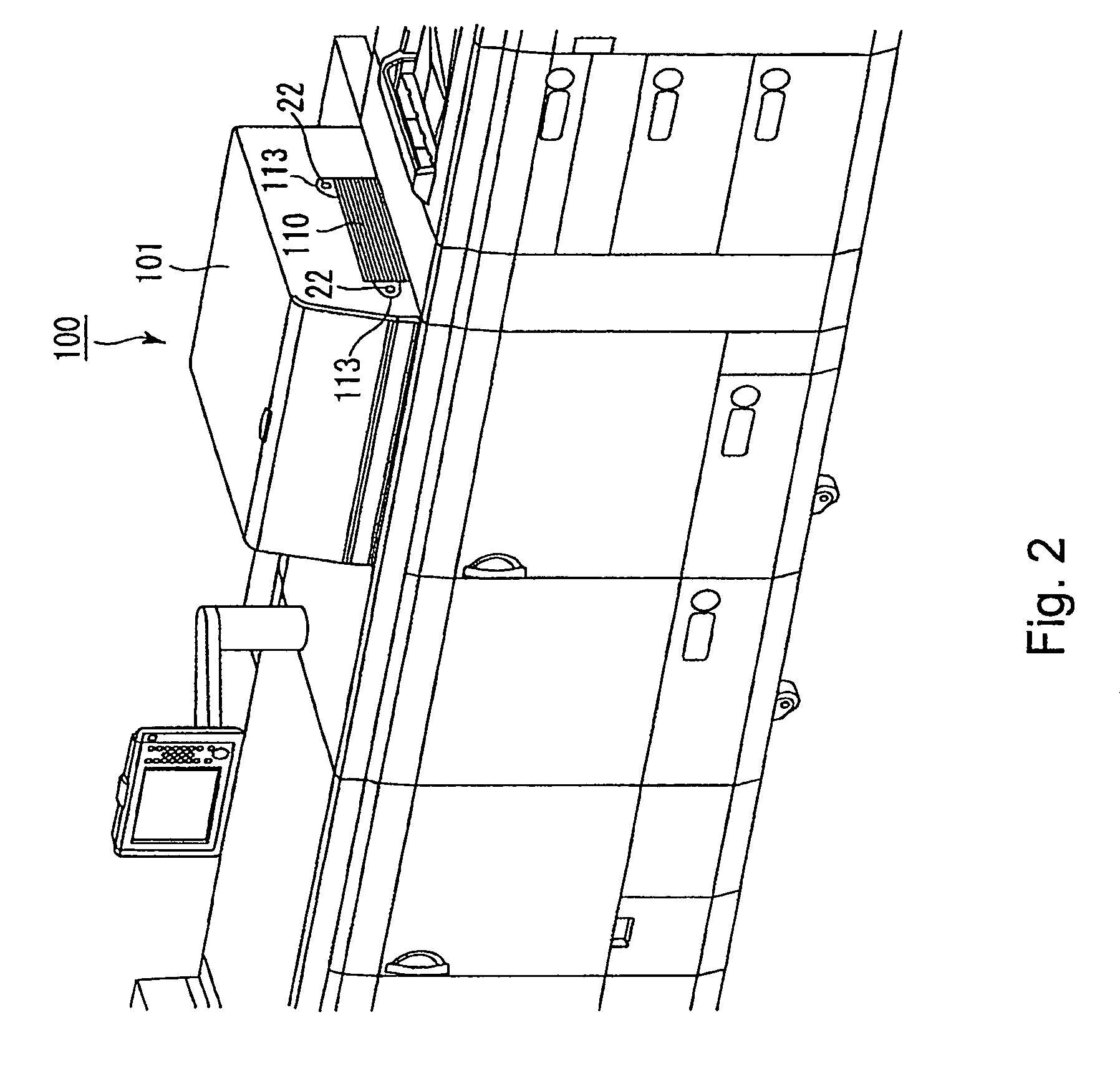
[0026]FIG. 1 schematically shows a structure of an image forming apparatus in the state of standard equipment according to an embodiment of the present invention. The image forming apparatus 100 of this embodiment is a full color laser beam printer capable of forming a full-color image using an electrophotographic type.

[0027]A main assembly of the apparatus 101 of the image forming apparatus 100 is provided therein with first, second, third and fourth image forming portions Py, Pm, Pc, Pb as image forming portions. Each of the first, second, third and fourth image forming portions Py, Pm, Pc, Pb form yellow, magenta, cyan and black images through electrophotographic image forming processes each including charging, exposure and development steps. The image forming apparatus 100 comprises a controller 19 as control means in the main assembly of the apparatus 101 The controller 19 includes a CPU as calculation processing m...

embodiment 2

[0088]Another embodiment of the present invention will be described. The fundamental structures and operations of the image forming apparatus of this embodiment are the same as those of Embodiment 1. Therefore, in the description of this embodiment, the same reference numerals as in Embodiment 1 are assigned to the elements having the corresponding functions in this embodiment, and the detailed description thereof is omitted for simplicity.

[0089]In this embodiment, there is provided temperature sensors 20y, 20m, 20c, 20b as temperature detecting means for detecting temperatures of the developers, in the developing devices 4y, 4m, 4c, 4b. When the optional cooling device 102 is mounted to the air supply opening 109, a controller 19 controls ON / OFF of the cooling device 102 in response to the detection result of the temperature sensors 20y, 20m, 20c, 20b. Also, the controller 19 controls various fans including a suction fan 106 provided in the main assembly side of the image forming a...


PUM


Abstract

An image forming apparatus includes a main assembly, an image forming portion for forming a toner image using an electrophotographic process, an air supply opening for fluid communication between an inside and an outside of the main assembly, and an air supply device for supplying ambient air into the main assembly through the air supply opening. In addition, an exhausting device discharges air from inside of the main assembly, and a mounting portion selectively mounts, to the air supply opening, one of a cooling device for taking the ambient air in and for decreasing a temperature of the air taken in, and a cover for partly blocking the air supply opening and forming an air passage portion. When the cooling device is mounted to the mounting portion, the air supply device supplies the cooled air into the main assembly, and when the cover is mounted to the mounting portion, the air supply device supplies the ambient air directly into the main assembly through the air passage portion of the cover. When the cooling device is not mounted to the mounting portion, a control device continues air supply from the air supply opening irrespective of a detected temperature, and when the cooling device is mounted to the mounting portion, the control device controls on and off of the cooling device on the basis of an output of the detecting device, and on and off supply of air from the air supply opening in interrelation with the cooling device.

Description

FIELD OF THE INVENTION AND RELATED ART[0001]The present invention relates to an image forming apparatus such as a copying machine, a printer or the like using an electrophotographic type.[0002]It relates more particularly to an image forming apparatus having a supply and exhaust system for cooling an inside of a main assembly of the apparatus.[0003]In an image forming apparatus of an electrophotographic type, a toner image formed on an electrophotographic photosensitive member (photosensitive member) in an image forming portion is transferred onto a surface of the recording material such as recording paper directly or by way of an intermediary transfer member.[0004]The toner image is fixed on the surface of the recording material by heating the recording material carrying the toner image by a fixing device.[0005]The heat of the fixing device is not only applied to the recording material but also is radiated in the inside of the main assembly of the image forming apparatus, and there...

Claims


Application Information

Patent Timeline
Patent Type & Authority Patents(United States)
IPC IPC(8): G03G21/20G03G15/00
CPCG03G21/203G03G21/206G03G2221/1645
Inventor NISHINO, YOSHIROSUZUKI, KENJI
Owner CANON KK
Learn More