Split blade housing for power operated rotary knife

a technology of rotary knives and split blades, which is applied in the direction of metal working equipment, etc., can solve the problems of shortened blade and pinion gear life, undesirable debris collection in the region of the meshing of the pinion gear and knife blade drive teeth, and increased vibration of the knife during operation, so as to facilitate the removal of the knife blade and expand the diameter

Active Publication Date: 2014-03-04
BETTCHER INDUSTRIES
View PDF5 Cites 46 Cited by
  • Summary
  • Abstract
  • Description
  • Claims
  • Application Information

AI Technical Summary

Problems solved by technology

Collecting debris materials in the region of the meshing of the pinion gear and knife blade drive teeth is undesirable because the heat generated by the driving engagement tends to “cook” the debris creating a sticky build up on the pinion gear and drive teeth and generating even more heat.
Moreover, such a build up of debris and sticky materials may lead to increased vibration of the knife during operation and shortened blade and pinion gear life, all of which are detrimental to rotary knife performance.

Method used


Image

  • Split blade housing for power operated rotary knife
  • Split blade housing for power operated rotary knife
  • Split blade housing for power operated rotary knife

Examples


Embodiment Construction

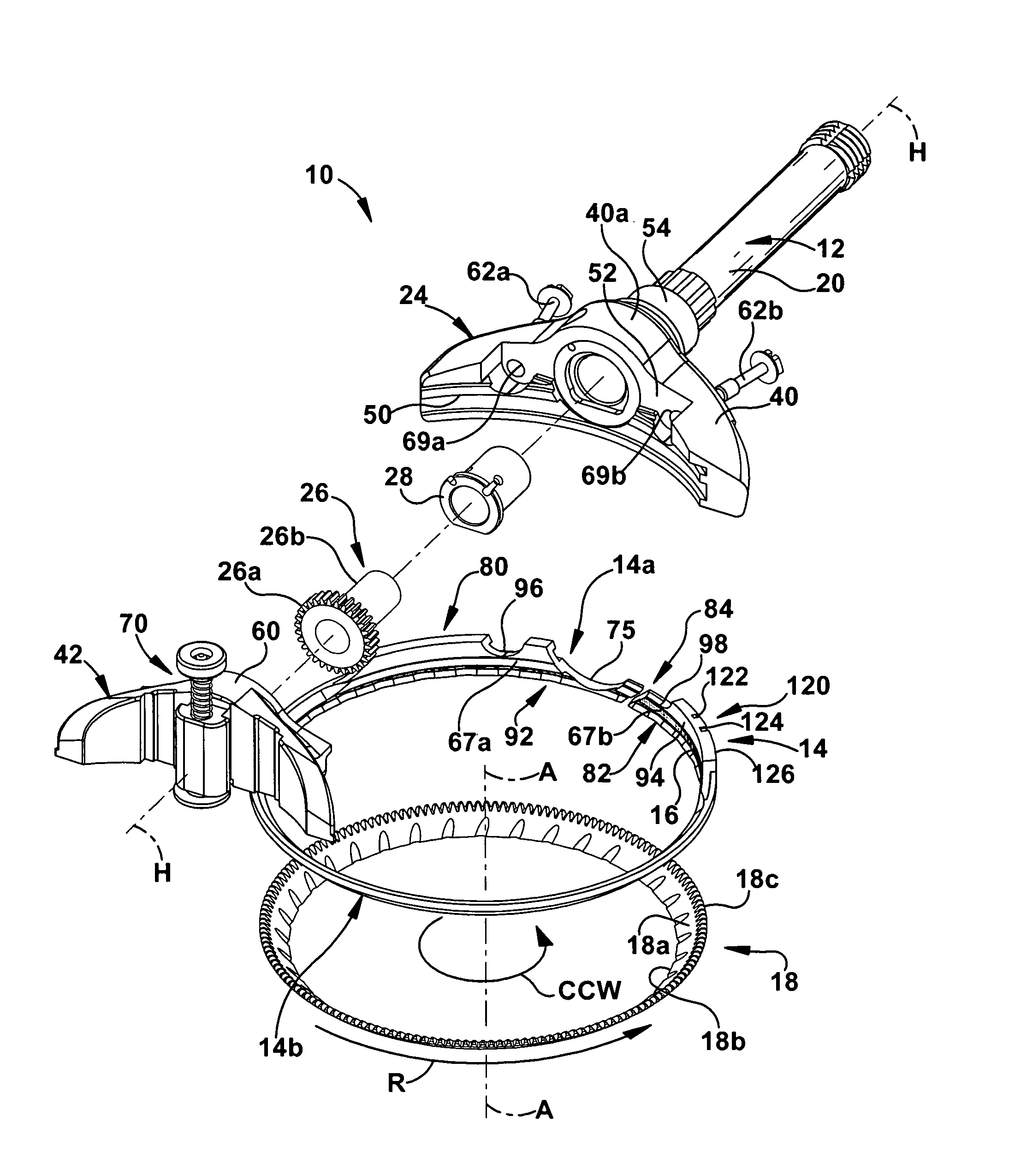
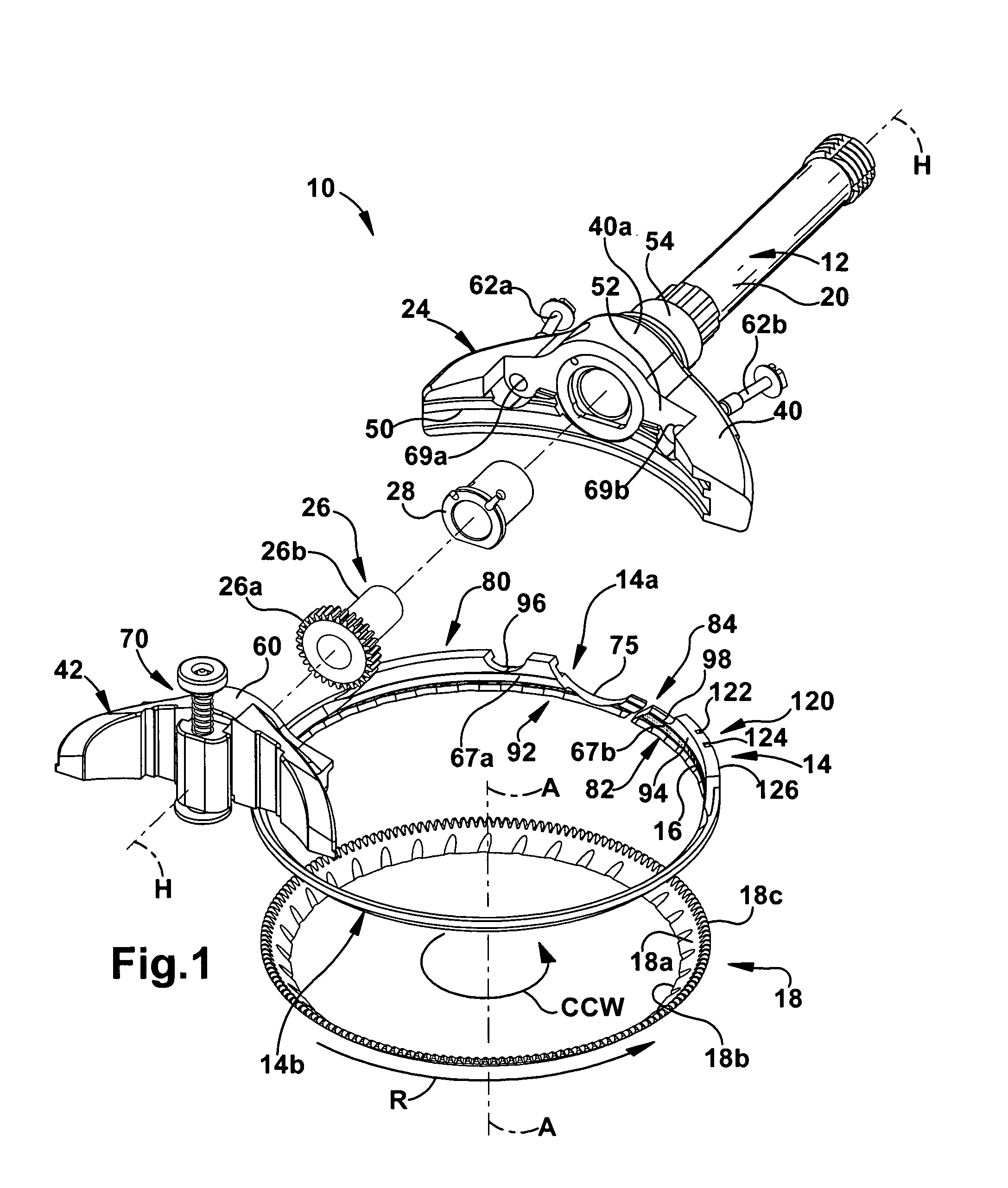
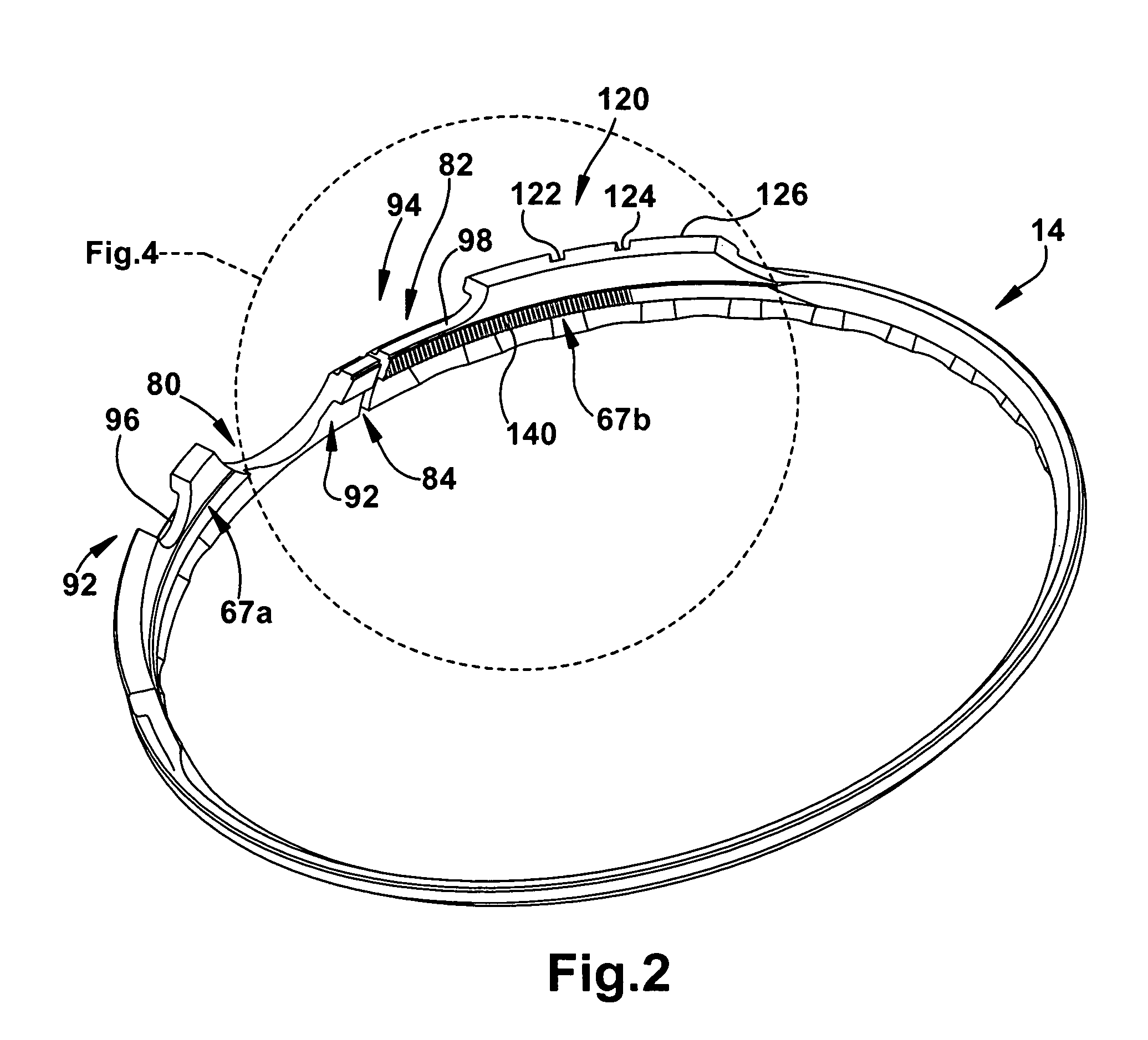
[0027]A power operated rotary knife 10 of the present invention is shown generally at 10 in FIG. 1. The knife 10 comprises a handle assembly 12, a generally ring-shaped, split blade housing 14 supported by the handle assembly 12, and an annular knife blade 18 supported by the blade housing 14 for rotation about an center axis of rotation A-A. The illustrated knife is connected to a remote electric motor by a flexible drive shaft so that the blade 18 is driven from the electric motor. The motor and drive shaft may be of any suitable or conventional construction and are not illustrated. It should be appreciated that other means may be employed to drive the blade 18. For example, an air motor may be mounted in the handle assembly 12 and connected to a source of pressurized air via a suitable hose, or an electric motor may be mounted in the handle assembly 12 and connected to a power source by a power cord. It is the intent of the present invention to cover all such drive systems.

[0028]...


PUM


Abstract

A split blade housing adapted to support an annular knife blade for rotation in a power operated rotary knife. The blade housing includes a mounting section and a body section extending from the mounting section and forming a ring. The mounting section of the split blade housing is adapted to be mounted to a handle assembly of the rotary knife and includes a recess providing clearance for a pinion gear that extends from the handle assembly to engage and drive the knife blade. The split blade housing includes an annular groove for rotatably supporting the knife blade, the groove defining a rotational plane of the knife blade. The split blade housing includes a split defining first and second end portions adjacent the split to facilitate removal of the knife blade from the housing. The housing split is peripherally offset from the mounting section recess and the split is transverse with respect to a center vertical axis of the blade housing.

Description

FIELD OF THE INVENTION[0001]The present invention relates to a split blade housing for a power operated rotary knife.BACKGROUND OF THE INVENTION[0002]Power operated rotary knives have been used in commercial meat processing operations to trim fat and connective tissue from meat, trim pieces of meat from bones, and to produce meat slices. Such knives usually comprise a handle, blade housing and a rotary knife blade. The knife blade includes an annular body and driving gear teeth projecting axially from the body oppositely from the blade cutting section. The blade housing supports and maintains the position of the blade relative to the knife as the blade is rotated. A pinion gear mounted in a head member of the handle engages the driving gear teeth to rotate the knife blade. The pinion gear, in turn, is driven by a long, flexible drive shaft that extends through the handle. The knife operator wields the knife relatively freely at a meat cutting work station that is remote from the dri...

Claims


Application Information

Patent Timeline
Patent Type & Authority Patents(United States)
IPC IPC(8): B26B7/00
CPCB26B25/002
Inventor WHITED, JEFFREY A.BOZZI, RICHARD P.
Owner BETTCHER INDUSTRIES
Why Eureka
Try Eureka