Sprint car wing

a technology of sprint cars and wing assemblies, which is applied in the direction of roofs, vehicle arrangements, transportation and packaging, etc., can solve the problems of affecting the efficiency of the wing, causing turbulence, and affecting the air flow around the wing, so as to increase the downforce of the car, reduce the impact of the wing, and reduce the effect of wing impa

Inactive Publication Date: 2014-03-04
JEFFREY LYNTON
View PDF6 Cites 3 Cited by
  • Summary
  • Abstract
  • Description
  • Claims
  • Application Information

AI Technical Summary

Benefits of technology

[0008]It is therefore a primary object, feature, and / or advantage of the present invention to provide an apparatus that overcomes the deficiencies in the art.
[0009]It is another object, feature, and / or advantage of the present invention to provide an improved sprint car wing having a wing belly of non-uniform thickness across the width of the wing to provide selective downforce.
[0010]It is yet another object, feature, and / or advantage of the present invention to provide an improved sprint car wing that does not include external struts to connect the side boards to the wing belly.
[0011]It is still a further object, feature, and / or advantage of the present invention to provide an improved sprint car wing that complies with the rules and regulations of the racing series, yet that has an enlargeable surface area for sideforce.
[0012]It is still another object, feature, and / or advantage of the present invention to provide an improved sprint car wing that provides increased downforce to the car.
[0013]It is another object, feature, and / or advantage of the present invention to provide an improved sprint car wing that improves the turning of the car.

Problems solved by technology

If the pressures were allowed to mix, a whirling vortex would be produced, which affects the efficiency of the wing by reducing downforce, increasing drag and in some circumstances causing lift.
These struts can create turbulence, drag, and bad air flow around the wing.

Method used


Image

  • Sprint car wing
  • Sprint car wing
  • Sprint car wing

Examples


Embodiment Construction

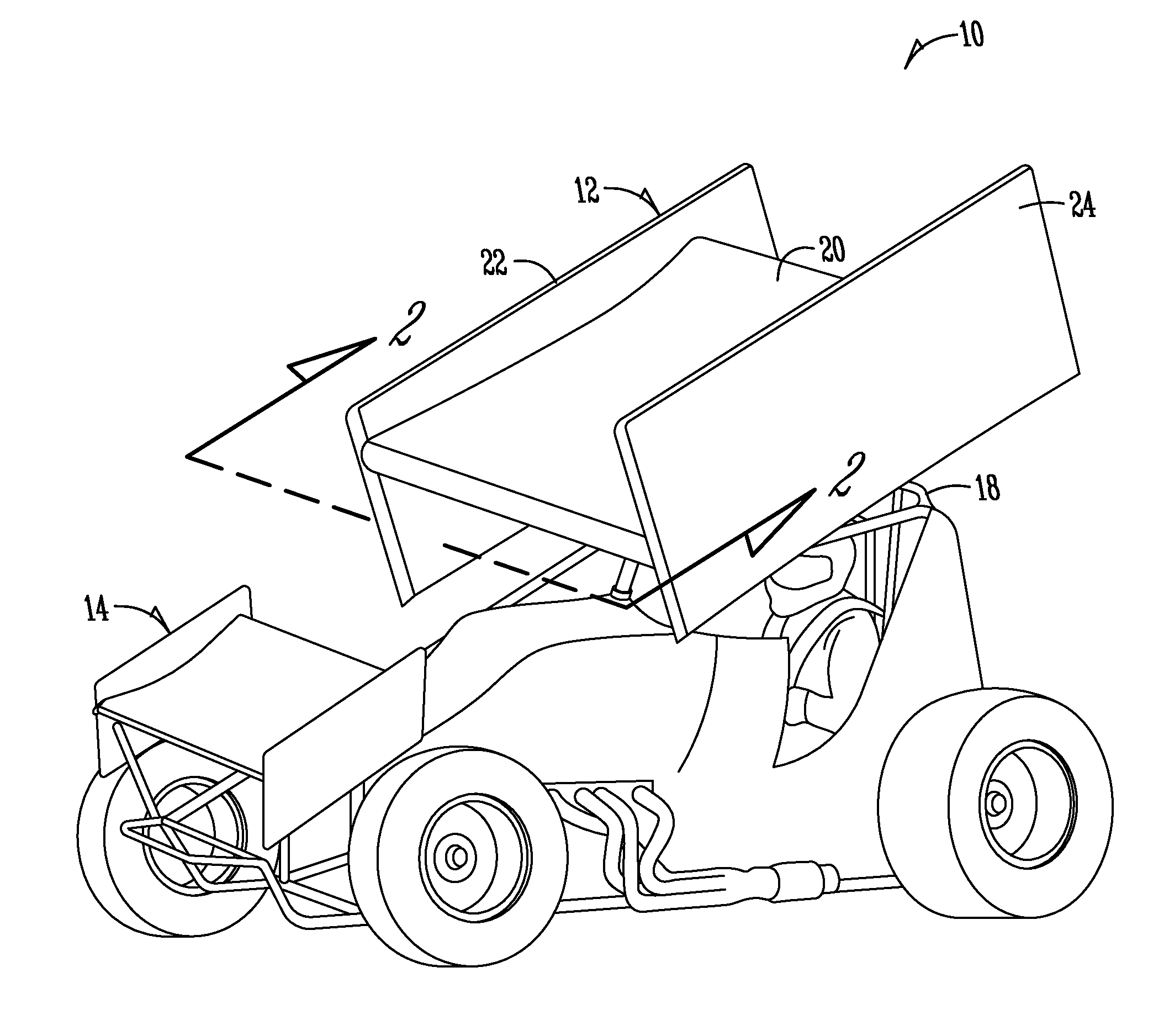
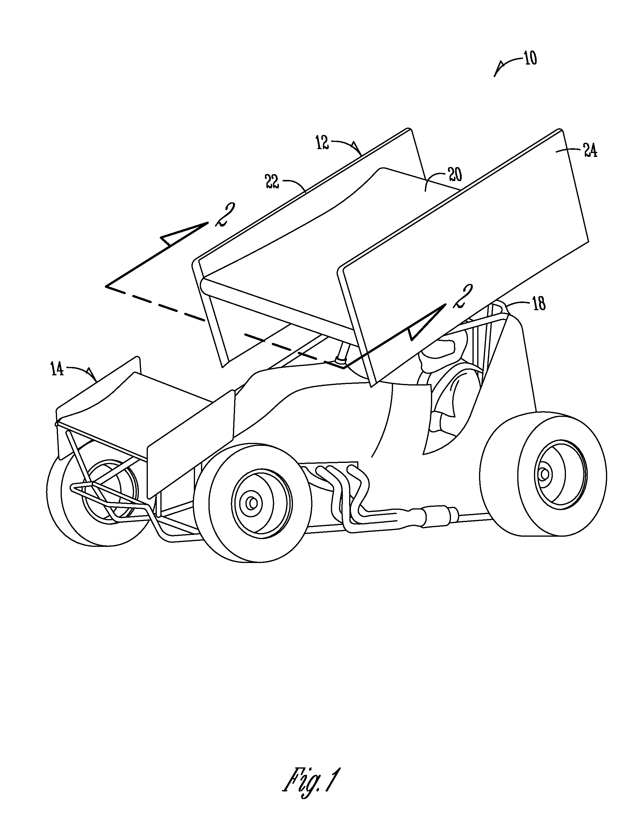
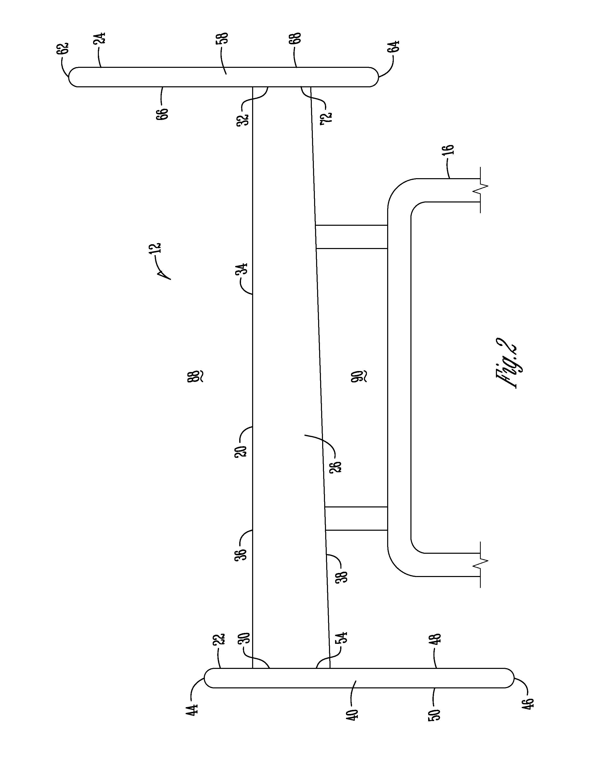
[0025]FIG. 1 is a perspective view of a sprint car type race car 10 having a top wing assembly 12 and a nose or front wing assembly 14. The top wing assembly includes generally a wing belly 20 and left and right side boards 22, 24. The nose wing is similar in construction to the top wing. The wings are mounted to the roll cage 18 of the sprint car 10, with the top wing 12 being mounted via a wing mount 16. The wing belly 20 acts like an upside down aircraft wing, creating down force instead of lift. The wing assembly 12 generate down force due to the air pressure differential between top and bottom surfaces of the wing. Due to the shape and angle of a tact of the wing, the air below the wing travels faster than that above, meaning that its air pressure will be lower. The speed of the air above the wing is either not changed or slowed by the shape of the wing, meaning the pressure of the air above the wing is higher than the air flowing under the wing. The down force is created as th...


PUM


Abstract

A sprint car wing or wing assembly is provided. The wing, which is known as a top wing, includes a wing belly and left and right side boards attached generally perpendicular to the wing belly. The wing belly includes a non-uniform thickness along its width to create downforce for the car. The right and left side boards are positioned mostly below and above the wing belly to aid in the creation of downforce, and also to provide the car with a sideforce during cornering. The side boards include a flexible surface, which will curve or bow to create greater sideforce. The side boards also house mounting frames of the wing assembly to mount the side boards to the wing belly.

Description

FIELD OF THE INVENTION[0001]The present invention relates generally to car wings. More particularly, but not exclusively, the present invention relates to the top wing assembly of a sprint car type race car, and a method of making the same.BACKGROUND OF THE INVENTION[0002]Sprint car wings are one of the defining features of the race cars. The wings, more specifically known as the top wing, are generally five foot by five foot, and are mounted above the head of the driver of the car. The wings provide downforce and safety for the cars. Furthermore, sprint cars may include smaller front wings or nose wings to help balance the race car and to keep the front of the car planted to the track.[0003]The top wings act like upside down aircraft wings, creating downforce instead of lift. A wing generates downforce due to the air pressure differential between the top and bottom surfaces of the wing. Due to the shape and angle of attack of the wing, the air below the wing travels faster than tha...

Claims


Application Information

Patent Timeline
Patent Type & Authority Patents(United States)
IPC IPC(8): B62D35/00
CPCB62D35/00B62D37/02
Inventor JEFFREY, LYNTON
Owner JEFFREY LYNTON
Why Eureka
Try Eureka