Illumination device and method

a technology for illumination devices and firearms, which is applied in the direction of ammunition loading, lighting and heating apparatus, butts, etc. it can solve the problems of attaching a flashlight on one side of the gun, so as to achieve more stable and accurate effect, limiting the utility of their other hand

Inactive Publication Date: 2014-03-04
SELLMARK CORP
View PDF11 Cites 44 Cited by
  • Summary
  • Abstract
  • Description
  • Claims
  • Application Information

AI Technical Summary

Benefits of technology

[0004]When security personnel, such as police, investigate dark areas under threat of violence, they often hold their firearm—often a handgun—with one hand and a flashlight with the other hand. This not only prevents them from grasping the firearm with both hands—which is known as being more stable and accurate than grasping the firearm with one hand—but also limits the utility of their other hand even if they were to maintain a one-handed grip on their gun.

Problems solved by technology

This not only prevents them from grasping the firearm with both hands—which is known as being more stable and accurate than grasping the firearm with one hand—but also limits the utility of their other hand even if they were to maintain a one-handed grip on their gun.
Laser sights are available for firearms, but such sights only provide a focused laser beam with which to check the aim of the gun against a target.
These sights fail to provide spread light that can illuminate an area.
Furthermore, holding or attaching a flashlight on one side of the gun limits the utility of the light emitted because half of the area is likely to still be relatively dark because of the shadow cast by the gun itself.
Flashlights are also often bulky compared to firearms.
Flashlights are also not ergonomically designed to be operated in conjunction with a firearm, even when attached to the firearm.
When the flashlight is not attached to the firearm, it is even more difficult to turn the light on and off, point the flashlight, and hold and aim the gun all at the same time even with two hands.
These lights also often take large enough batteries, causing a significant change in the weight distribution of the handgun which in turn affects the ability to hold and aim the firearm.
Handguns typically have a center of mass near the front of the handle, so the shift of the center of mass with a barrel-mounted flashlight gives the handgun an unnatural, and unexpected forward-shifted balance.

Method used


Image

  • Illumination device and method
  • Illumination device and method
  • Illumination device and method

Examples


Embodiment Construction

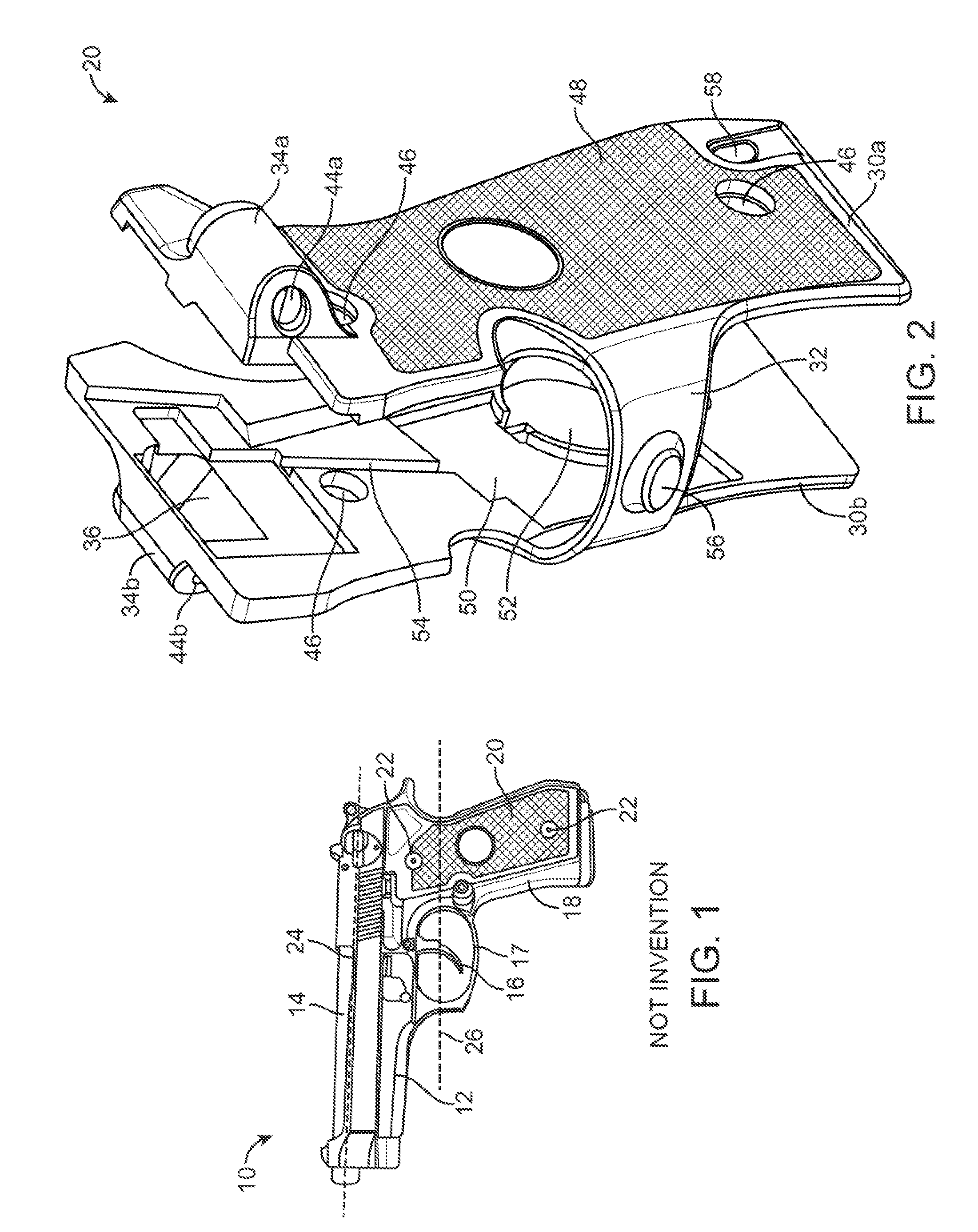
[0023]FIG. 1 illustrates that a gun 10 can have a receiver or frame 12, barrel 14 and trigger 16. The trigger 16 can be partially surrounded by a trigger guard 17. The gun 10 can be a handgun (as shown), rifle, or shotgun. The frame 12 can have a grip 18. The grip 18 can be integral with or attached to and detachable from the frame 12. The grip 18 can be integral with or attached to a stock.

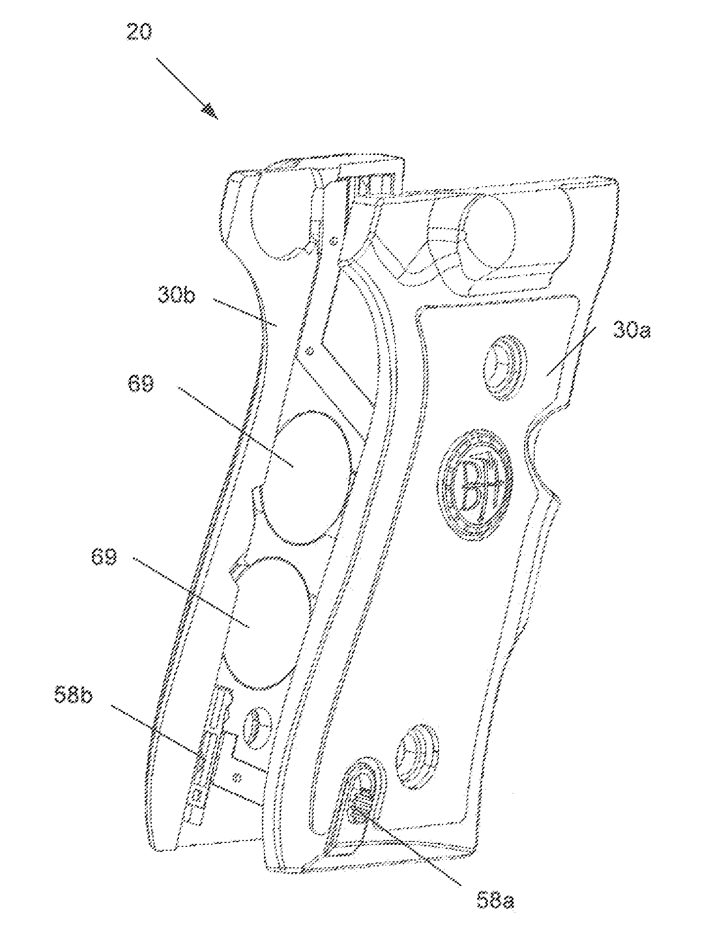
[0024]The grip 18 can have a grip cover 20. The grip cover 20 can be integral with or attached to and detachable from the grip 18. Attachment elements or fasteners, such as brads, bolts or screws 22 can extend through the grip cover 20 and threadably attach to the grip 18, for example, removably attaching the grip cover 20 to the grip 18.

[0025]The barrel 14 can have a barrel longitudinal axis 24. A trigger finger axis 26 can be a lateral projection of the plane defined by the trigger finger when the hand is holding the grip 18 and the trigger finger is placed on the trigger 16. The trigger finger...


PUM


Abstract

An illumination device for use with a firearm and a method of using the same are disclosed. The illumination device can include a gun grip cover configured to attach to a gun grip. The illumination device can have a first illumination element extending to the left of the gun grip cover and a second illumination element extending to the right of the gun grip cover. The illumination elements can deliver a spread of light to illuminate a large area. The illumination elements can be laterally adjacent to the barrel. The illumination elements can be controlled by a control switch positioned below the trigger.

Description

BACKGROUND[0001]1. Technical Field[0002]The disclosure relates to an illumination device for a firearm. More specifically, the disclosure relates to a gun grip cover having an integrated light.[0003]2. Summary of the Art[0004]When security personnel, such as police, investigate dark areas under threat of violence, they often hold their firearm—often a handgun—with one hand and a flashlight with the other hand. This not only prevents them from grasping the firearm with both hands—which is known as being more stable and accurate than grasping the firearm with one hand—but also limits the utility of their other hand even if they were to maintain a one-handed grip on their gun.[0005]Laser sights are available for firearms, but such sights only provide a focused laser beam with which to check the aim of the gun against a target. These sights fail to provide spread light that can illuminate an area.[0006]Furthermore, holding or attaching a flashlight on one side of the gun limits the util...

Claims


Application Information

Patent Timeline
Patent Type & Authority Patents(United States)
IPC IPC(8): F41G1/34
CPCF41C23/10F41G1/35F41G1/34
Inventor IZUMI, TERRYGETTINGS, ADAM M.GETTINGS, NATHAN D.
Owner SELLMARK CORP
Why Eureka
Try Eureka