Method and system for collecting cells following laser microdissection

a laser microdissection and laser microdissection technology, applied in the field of laser microdissection methods and systems, can solve the problems of high time consumption, low efficiency and precision, and high difficulty

Active Publication Date: 2014-03-04
MOTIC CHINA GRP CO LTD
View PDF18 Cites 8 Cited by
  • Summary
  • Abstract
  • Description
  • Claims
  • Application Information

AI Technical Summary

Benefits of technology

[0028]The novel method and apparatus of the present invention consists of the non-contact transfer of target regions from a target object, such as cells in a mounted tissue section on a prepared slide, by electrostatic repulsion of the small mass of the target regions by the static electric charge of the much larger dielectric membrane onto which the tissue sections are mounted, and the subsequent electrostatic cling of the laser-microdissected target regions to a polar collection material, such as an agar gel, positioned above the prepared slide. The electrostatic repulsion of the laser-dissected small mass effectively acts as a propulsion actuator of the target regions, overcoming the force of gravity sufficiently long enough for the target regions to reach and adhere to the agar gel in the collection container suspended above the prepared slide and the tissue sections, cells, or other material attached to it.

Problems solved by technology

This method possessed many disadvantages, including a high degree of difficulty, high time consumption, low efficiency and precision, high demand for skills of the operator, and low bioactivity of separated biological samples caused by mechanical injury.
The main disadvantages of this technique include mechanical damage on biological samples during separation and low precision because the film may also stick cells around target regions.
Disadvantages for this technique include the additional time required to defocus the laser, then re-focus on the sample, and the possibility that the UV laser beam may strike the middle of the cells, where the DNA and RNA may be altered by the laser.
The membrane used in this method may lead to higher cost.

Method used


Image

  • Method and system for collecting cells following laser microdissection
  • Method and system for collecting cells following laser microdissection
  • Method and system for collecting cells following laser microdissection

Examples


example 1

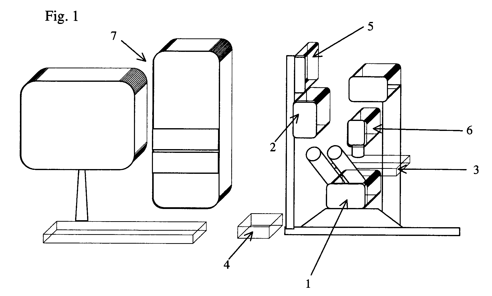
[0046]In this example, a special inverted 20× fluorite objective in microscope 1 can be used for laser microdissection. This objective has a high transmission of a 337 nm ultraviolet laser beam. The researcher can use about 61 percent of the total laser power to cut freshly-prepared frozen tissue sections and an approximately six um wide cut line may be achieved.

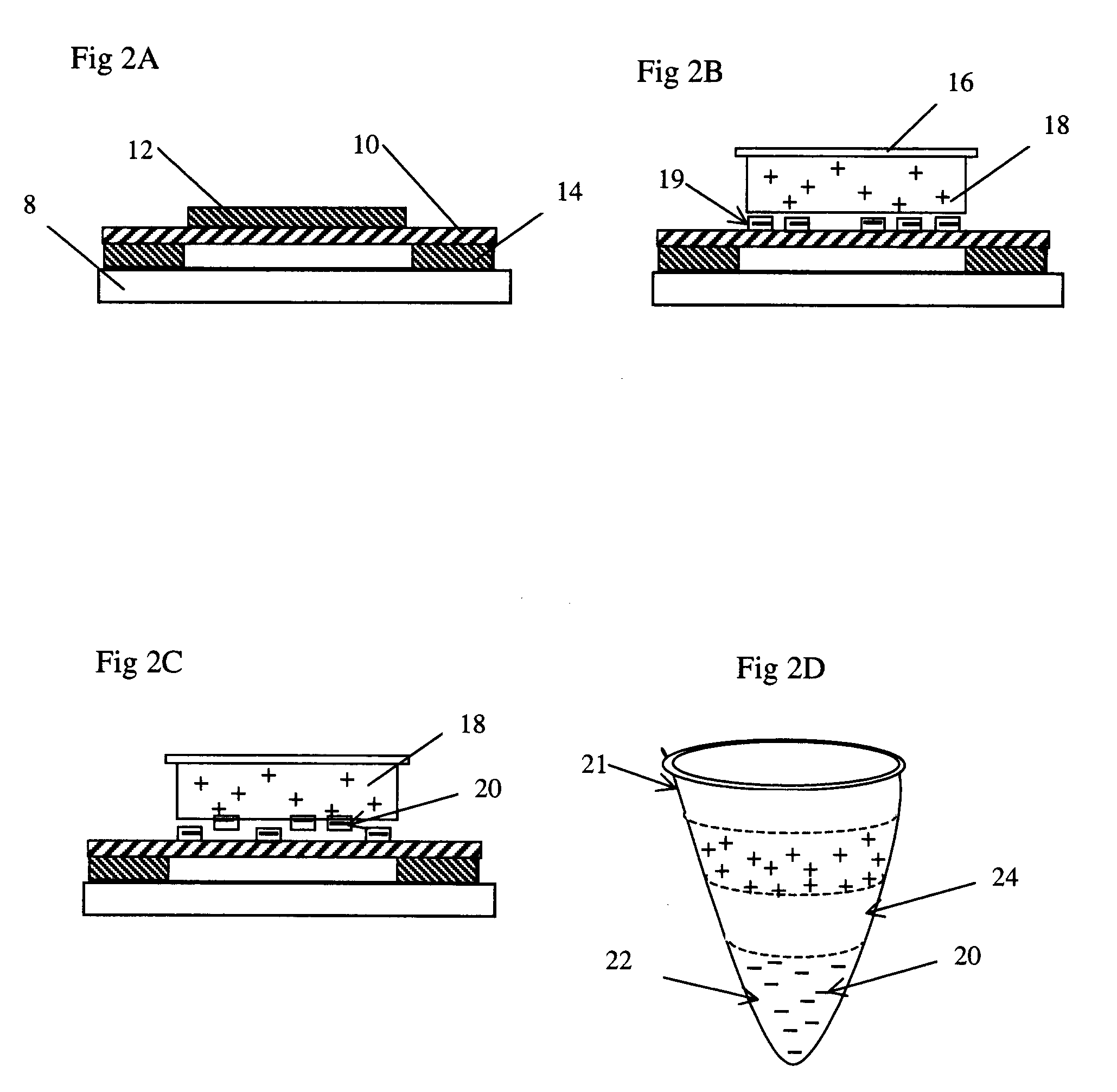
[0047]For the purpose of downstream DNA analysis of tumor cells, eight urn thick frozen tissue sections derived for hepatic carcinoma are prepared in the pathological lab following the standard treatment and mounted on the polyimide film 10 on the regular one mm thick glass slides 8.

[0048]Frozen sections 12 are fixed in 70 percent ethanol for 15 seconds, dipped in water, stained by a conventional method (e.g. hematoxylin), and dipped into 50 percent, 70 percent and 100 percent ethanol, sequentially. The sections 12 are exposed to air to dry for five minutes. The slides can now be used at once (even if they are somewhat wet) ...

example 2

[0051]In this example, a special 100× oil immersion objective can be used on microscope 1 to isolate and collect several cell groups of interest, even single cell. The collected cells can be extracted and subsequentially subjected to the downstream RNA analysis of tumor cells.

[0052]As described as the Example 1, approximately eight um thick frozen sections derived from breast carcinoma tissue are prepared onto the polyimide film 10 on a 0.17 mm thin coverslip instead of a 1.0 mm glass slide, which is special to match 100× oil immersion objective. Frozen sections 12 are treated as described as Example 1.

[0053]Before microdissection, frozen sections 12 are disposed upright on the motorized stage 3 in the present laser microdissection system. A small amount of immersion oil, such as anisol, is added on the lens surface of the 100× oil immersion objective, and the 100× objective is elevated toward the back of the glass coverslip as closely as possible. After observing and outlining all ...


PUM

PropertyMeasurementUnit
thickaaaaaaaaaa
thicknessaaaaaaaaaa
gap distanceaaaaaaaaaa

Abstract

A method of collecting target regions from a target object is described. The method in one embodiment comprises mounting a negatively-charged membrane on a first side of a substrate, mounting a target object on the membrane, positioning a collection material adjacent to the target object, and passing a laser beam from a second side of the substrate, through the substrate, the membrane, and the target object, to dissect target regions from the prepared tissue section, whereby the dissected target regions adhere to the collection material. In another embodiment, the present invention is a system for collecting target regions from a target object. In one embodiment, the system comprises a substrate having a first side and a second side, a negatively-charged membrane adhered to the first side of the substrate, and a collection material mountable adjacent to the membrane. In another embodiment, the system further comprises an inverted microscope, a stage for holding the substrate over the microscope, a generator operable to generate a laser beam to pass through the substrate from the second side and to dissect target regions from a target object mounted on the membrane, whereby the dissected target regions adhere to the collection material. In the preferred embodiments, the target objects are tissues and the target regions are cells.

Description

PRIORITY[0001]This application is a national-phase entry of PCT / CA2006 / 000838, filed May 19, 2006, and claims priority from Application No. 200510034838.3, filed in the Republic of China on May 20, 2005, the disclosure of which is incorporated herein in its entirety.BACKGROUND OF THE INVENTION[0002]The present invention relates to a new method and system for non-contact collection of cells or other target regions following laser microdissection from tissue sections, tissue-derived cell preparations, other biologically-derived materials, or non-biological materials that have been mounted onto a specially-prepared slide.[0003]In the field of life science, selecting and successfully collecting homogeneous cells of interest without contamination from heterogeneous tissue samples is a precondition for the accurate and specific isolation and characterization of biologically relevant molecules that pertain to the normal, diseased, or malignant state of the cell population.[0004]The earlies...

Claims


Application Information

Patent Timeline
Patent Type & Authority Patents(United States)
IPC IPC(8): G01N1/40G01N1/04C12Q1/68G01N1/30G01N1/18
CPCG02B21/34G01N1/4077C12Q1/68G01N1/286C12M47/04G01N1/30G02B21/32C12Q1/6806G01N1/2813G01N1/04G01N2001/284Y10T436/25375C12M1/00C12N1/00G01N1/28
Inventor YEUNG, RICHARD
Owner MOTIC CHINA GRP CO LTD
Why Eureka
Try Eureka