Wind turbine and a shaft for a wind turbine

a wind turbine and shaft technology, applied in the direction of shafts, applications, engine fuctions, etc., can solve the problems of wear and tear of the damaged element, take out of service, etc., and achieve the effect of facilitating the design of the rotor support type of the wind turbin

Inactive Publication Date: 2014-03-04
ENVISION ENERGY DENMARK
View PDF12 Cites 848 Cited by
  • Summary
  • Abstract
  • Description
  • Claims
  • Application Information

AI Technical Summary

Benefits of technology

[0034]1. Increased bending flexibility reduces forces on bearings in wind turbine.
[0035]2. Increased buckling stability of the shaft possibly leads to reduced materials required for construction.

Problems solved by technology

One of the disadvantages of such a system is that in order to compensate for vibrations and bending moments transferred through the hub shaft from the hub, the generator and the gearbox must be mounted on vibration damping elements which are coupled to the machine housing.
Such damping elements are subject to wear and tear during the lifetime of the system, often requiring replacement every 3-5 years in a relatively costly maintenance operation, at which time the turbine must be taken out of service for an extended period of time.

Method used


Image

  • Wind turbine and a shaft for a wind turbine
  • Wind turbine and a shaft for a wind turbine
  • Wind turbine and a shaft for a wind turbine

Examples


first embodiment

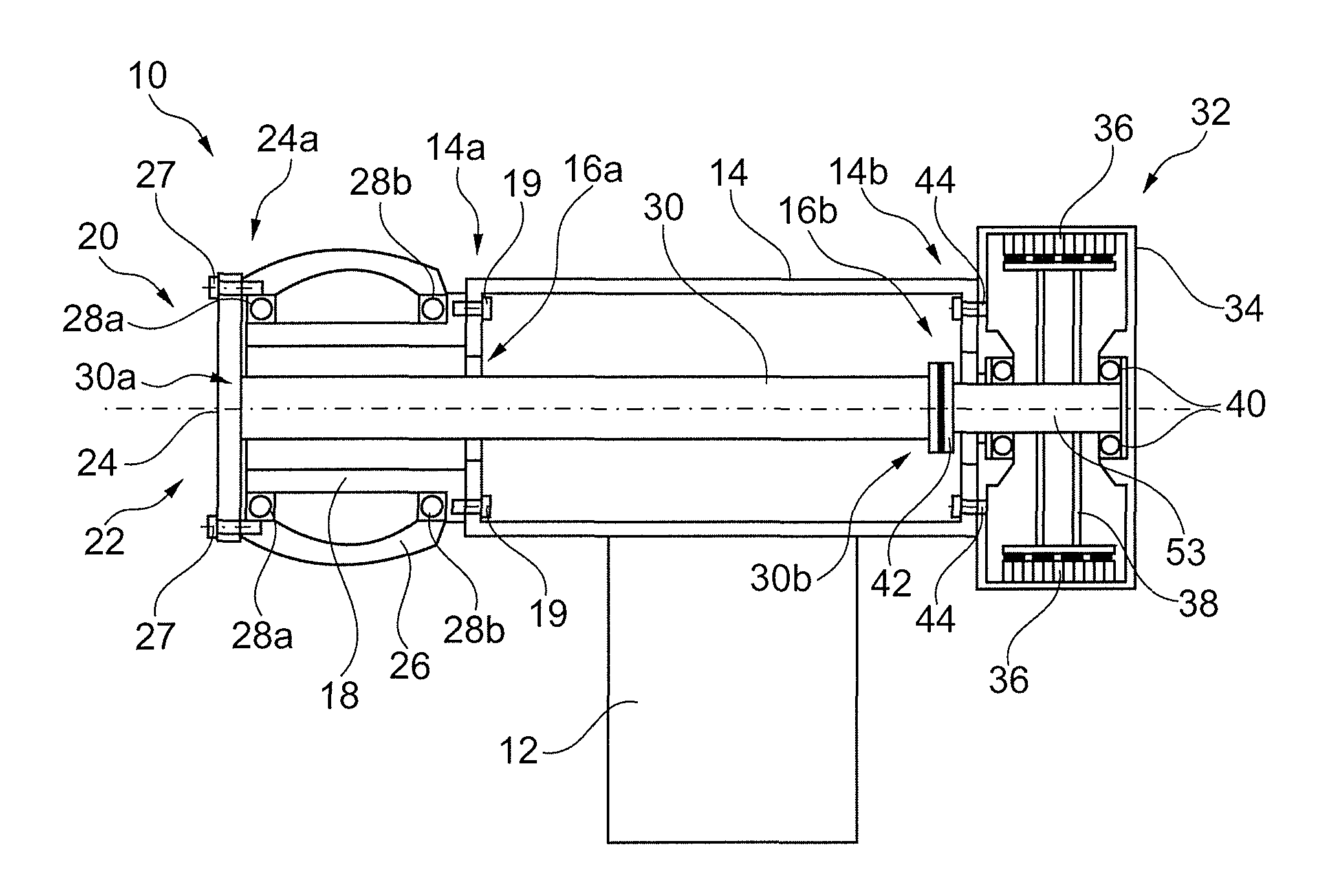
[0139]With reference to FIG. 1, a drive shaft for a wind turbine according to the invention is indicated generally at 100. The shaft 100 comprises a hollow cylindrical body 102 having first and second ends 102a, 102b. A raised helical rib 104 is provided on the external surface of the shaft body 102, the rib 104 extending along the body of the shaft from the first end 102a to the second end 102b. The helical rib 104 is provided having a helix angle of approximately 45° (i.e., the angle between the helix and the central axis of the shaft).

[0140]The presence of a suitable shaping of the shaft body, e.g., rib 104, allows for the shaft 100 to be more easily bent relative to a known straight-walled shaft.

second embodiment

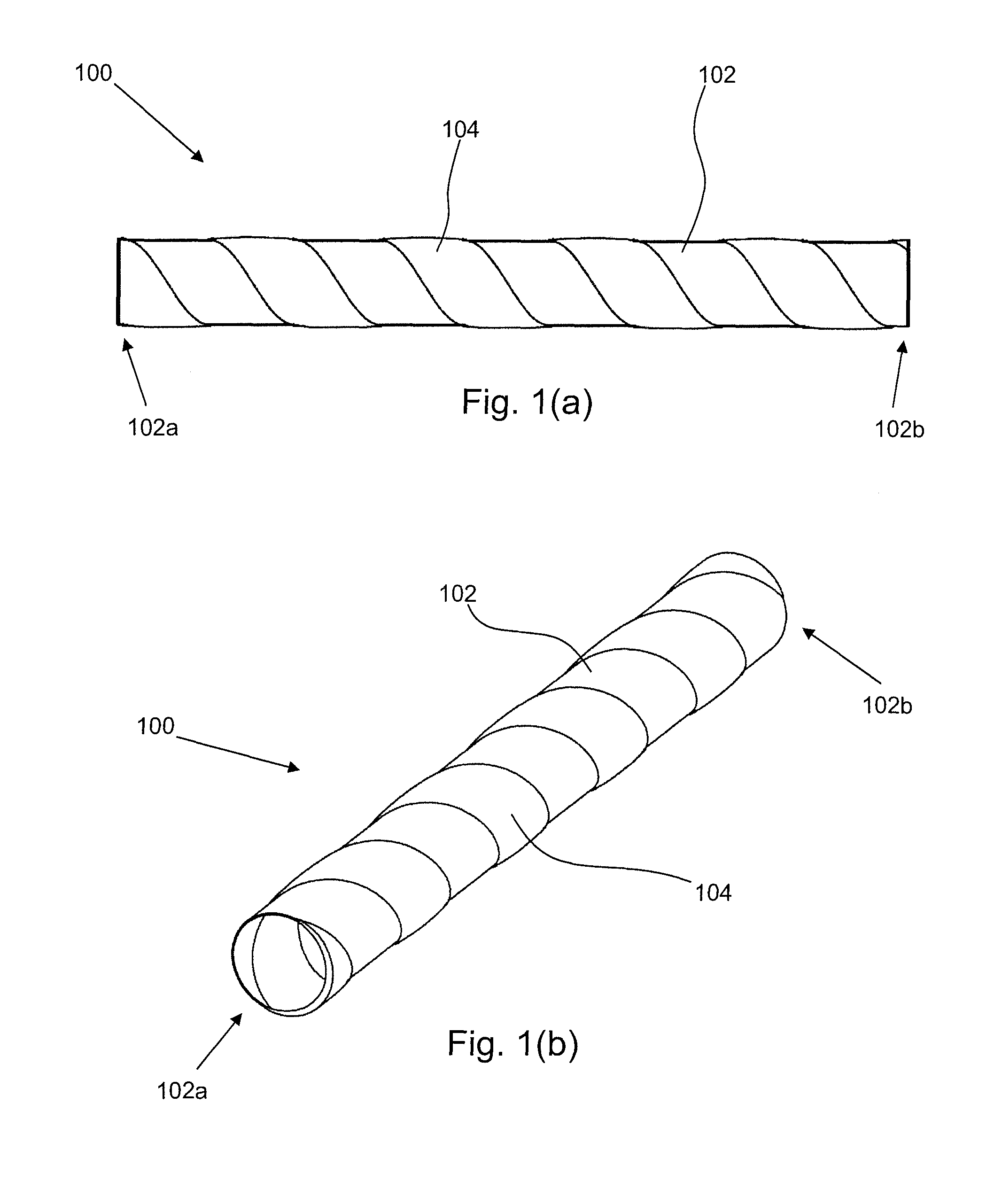
[0141]FIG. 2 illustrates a drive shaft, indicated generally at 200. Again, the shaft 200 comprises a hollow cylindrical body 202 having first and second ends 202a, 202b. A raised helical rib 204 is provided on the external surface of the shaft body 202, the rib 204 extending along the body of the shaft from the first end 202a to the second end 202b. In this embodiment, the helical rib 204 is provided having a helix angle of approximately 85° (i.e., the angle between the helix and the central axis of the shaft).

[0142]FIG. 3(a) shows an enlarged portion of a cross-sectional view of drive shaft 200. On the internal surface of the drive shaft body 202, a helical rib 206 is defined, corresponding to the helical rib 204 defined on the external surface of the shaft body 202. In this embodiment, the shaft can be seen to be ribbed on both the internal and external surfaces of the hollow shaft body 202.

[0143]It will be understood that various alternative shapes of the shaft body 102, 202 may ...


PUM

PropertyMeasurementUnit
lengthaaaaaaaaaa
lengthaaaaaaaaaa
outer diameteraaaaaaaaaa

Abstract

A drive shaft for a wind turbine is shaped so as to allow for increased bending of the shaft, while being suitable for transferring torque in a wind turbine system. An example of such a shaping is a drive shaft having a helical rib defined on the surface of the shaft. A wind turbine incorporating such a shaft, and a method of manufacture of such a shaft are also described.

Description

BACKGROUND OF THE INVENTION[0001]1. Field of the Invention[0002]The present invention relates to a shaft, in particular a drive shaft for a wind turbine power generator, and a wind turbine using such a shaft.[0003]2. Description of Related Art[0004]Rotor support-type wind turbines are a known alternative wind turbine design, wherein the structural load of the hub and rotor blades is provided by a fixed support shaft provided on the wind turbine main frame. As the hub is allowed to rotate freely about the support shaft, consequentially the structural load is transferred to the main frame while the torque provided by the spinning rotor blades is transferred to the generation system.[0005]U.S. Pat. No. 4,757,211 disclose a rotor support-type wind turbine wherein a rotor hub is mounted onto a cylindrical section of the machine housing, the structural load of the rotor hub being supported by the machine housing. A hub shaft extends from the hub to the gearbox, and is accordingly coupled ...

Claims


Application Information

Patent Timeline
Patent Type & Authority Patents(United States)
IPC IPC(8): H02P9/04F03D9/00
CPCF16C3/026F03D11/00B29C53/821B29C53/585B29C53/66B29L2016/00F05B2240/62F03D11/02F05B2270/1095Y02E10/722F05B2260/96F05B2250/25F16C2360/31F03D15/00F03D15/20F03D80/00F03D80/30F03D80/70Y02E10/72Y02P70/50
Inventor REBSDORF, ANDERS, VARMING
Owner ENVISION ENERGY DENMARK
Why Eureka
Try Eureka