
Friction estimation method

a friction estimation and tire technology, applied in vehicle tyre testing, brake systems, instruments, etc., can solve the problems of unfavorable safety improvement, unnecessarily frequent warnings, etc., to improve the reliability and legitimacy of warnings delivered

Active Publication Date: 2014-03-04
AALTO UNIV FOUND
View PDF22 Cites 12 Cited by
  • Summary
  • Abstract
  • Description
  • Claims
  • Application Information

AI Technical Summary

Benefits of technology

The invention provides a system for accurately estimating the maximum friction of a vehicle's tires and the road surface conditions, and for improving the driving dynamics and safety of the vehicle. The system uses sensor data from driving dynamics to track the friction properties of the tires and the road surface, and to provide drivers with more accurate and reliable information about the driving feel. The system can also integrate information from other vehicles to improve safety and make predictions about the grip of the tires. The invention also includes a method for anticipating braking accelerations and warning drivers about slippery conditions. The system can be used on any friction-driven vehicle, including heavy-duty combination vehicles, and can adapt to different road conditions.

Problems solved by technology

For example, on the basis of a mere sensor message, there will be unnecessarily frequent warnings in winter conditions about ice which is not more slippery than usual.
The warnings perceived to be futile do not improve safety, but are just a nuisance to the driver.

Method used


Image

  • Friction estimation method
  • Friction estimation method
  • Friction estimation method

Examples


Embodiment Construction

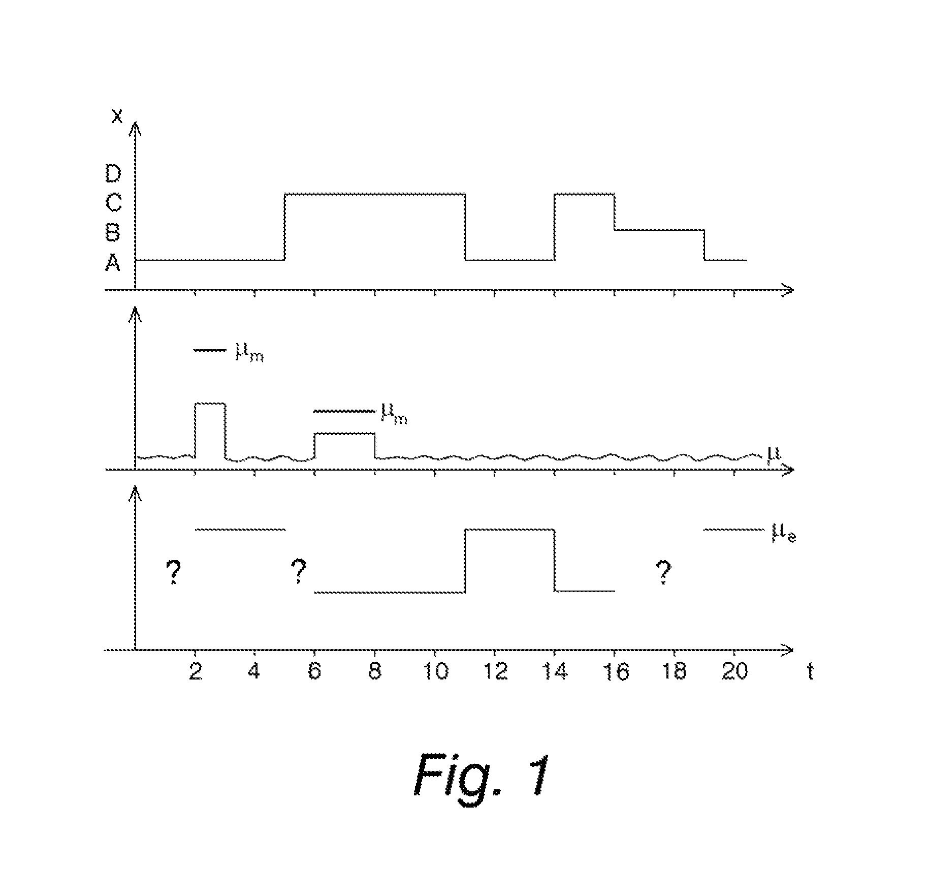
[0042]In the FIG. 1, the top graph is a road sensor's classification result X, varying in the example among classes A, B, C, and D. The true measuring result, however, is a multidimensional vector, which may comprise information for example about the reflection factors of a road sensor, the polarity of a reflection, and the directions of a reflection on various wavelengths of electromagnetic radiation, about temperature, humidity, etc. In addition, the road surface can be measured also outside the tires' traveling lines in order to enable a warning to be given about an inconsistent grip of the road. The quantity X can be for example a 10-dimensional classification result of 16-bit measuring results and a vector established by their frequency analysis. In practice, X acquires a considerable number of different values, and classification can be used for finding more quickly a corresponding old measuring result and for facilitating the selection of similar friction estimates.

[0043]The ...


PUM

PropertyMeasurementUnit
friction coefficientaaaaaaaaaa
frictionaaaaaaaaaa
road surface propertiesaaaaaaaaaa

Abstract

A method and apparatus for the estimation of maximum friction between a vehicular tire and a road surface via driving dynamics measurements and at least one sensor measuring the road surface, comprisingmeasuring road surface properties via a sensor;measuring the state of motion of a vehicle and a tire and concluding therefrom a momentary maximum friction coefficient when the tire is subjected to a sufficient friction force;storing a maximum friction estimate concluded from the above-mentioned measurements, along with measuring results regarding road surface properties measured at the moment of measurement;when the tire is not subjected to a friction force sufficient for measuring maximum friction, using, as a maximum friction estimate, the previously measured maximum friction estimate, such that an applied selection criterion for the maximum friction estimate is the newness as up-to-date as possible of the measuring result and a consistency of the road surface measuring result.

Description

CROSS-REFERENCE TO RELATED APPLICATIONS[0001]This application is a national stage filing under 35 U.S.C. 371 of PCT / FI2009 / 050749 filed Sep. 18, 2009 which International Application was published by the International Bureau in English on Mar. 25, 2010 and claims priority to Finnish Patent Application No. 20085883, filed on Sep. 19, 2008 which are both hereby incorporated herein in their entirety by reference.BACKGROUND OF THE DISCLOSURE[0002]1. Field of the Disclosure[0003]The invention relates to the estimation of tire friction in vehicles, particularly to the estimation of maximum friction available at a specific time. The knowledge regarding maximum friction is especially desirable in anticipatory warning and steering systems, in control of anti-lock brakes, in slip control systems, and in driving stability systems.[0004]2. Description of Related Art[0005]In the driving stability systems, ABS brakes and slippage control systems of vehicles, as well as for example in systems estim...

Claims


Application Information

Patent Timeline
Patent Type & Authority Patents(United States)
IPC IPC(8): G01M17/02B60T8/1763B60W40/06G01N19/02
CPCB60T8/172B60W40/068G01M17/02B60T2210/12B60T2210/13B60K28/16B60T8/17636B62D6/00G01N19/02
Inventor TUONONEN, ARI
Owner AALTO UNIV FOUND
Learn More