
Control device for internal combustion engine

a control device and internal combustion engine technology, applied in the direction of electrical control, process and machine control, instruments, etc., can solve the problems of poor fuel economy, inability to meet the requirements concerning various kinds of performance of the internal combustion engine with excellent balance, etc., to achieve the effect of sharp recovery and no reduction of catalyst purification performan

Inactive Publication Date: 2014-03-04
TOYOTA JIDOSHA KK
View PDF20 Cites 2 Cited by
  • Summary
  • Abstract
  • Description
  • Claims
  • Application Information

AI Technical Summary

Benefits of technology

The patent text discusses the issue of delay in changing air quantity due to changes in required air-fuel ratio. The text proposes various methods to reduce this delay, such as using a low-pass filter or performing weighted average processing. By doing so, torque variation can be minimized, resulting in a smoother and more stable operation of the engine.

Problems solved by technology

However, regulation of torque by ignition timing is effective only when the torque is reduced by retardation, and in such a case, worsening of fuel economy occurs.
More specifically, the requirements concerning various kinds of performances of the internal combustion engine cannot be satisfied with an excellent balance by only lessening the change speed of the required air-fuel ratio, or by simply adjusting the ignition timing.

Method used


Image

  • Control device for internal combustion engine
  • Control device for internal combustion engine
  • Control device for internal combustion engine

Examples


Embodiment Construction

[0031]An embodiment of the present invention will be described with reference to the drawings.

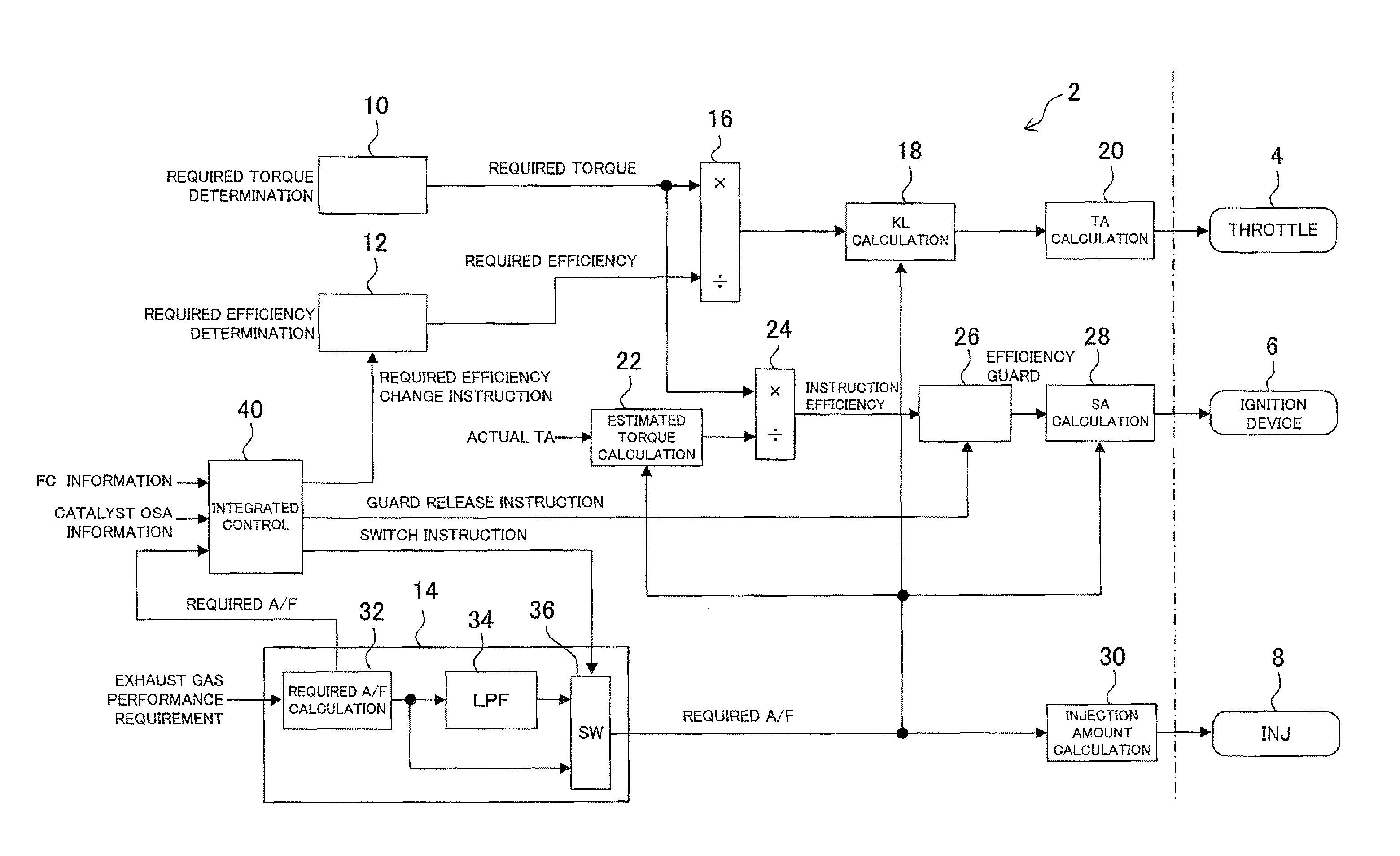
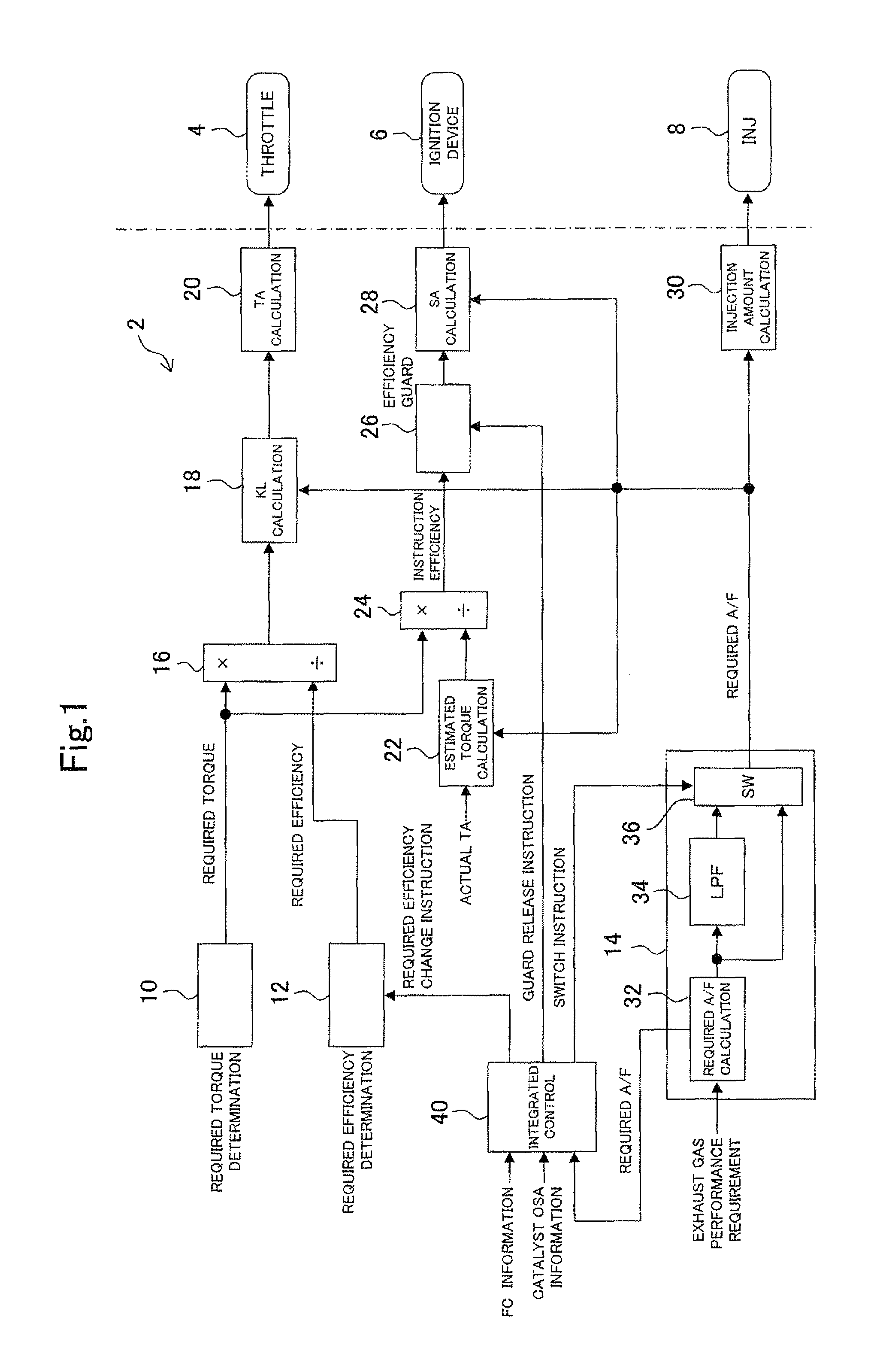
[0032]An internal combustion engine (hereinafter, an engine) which is an object to be controlled in the embodiment of the present invention is a spark ignition type four-cycle reciprocal engine. In an exhaust passage of the engine, a three-way catalyst for purifying exhaust gas is provided. A control device controls an operation of the engine by manipulating actuators included in the engine. The actuators which can be manipulated by the control device include an ignition device, a throttle, a fuel injection device, a variable valve timing mechanism, an EGR device and the like. However, in the present embodiment, the control device manipulates a throttle, an ignition device and a fuel injection device, and the control device manipulates these three actuators to control the operation of the engine.

[0033]The control device of the present embodiment uses torque, an air-fuel ratio and an efficie...


PUM


Abstract

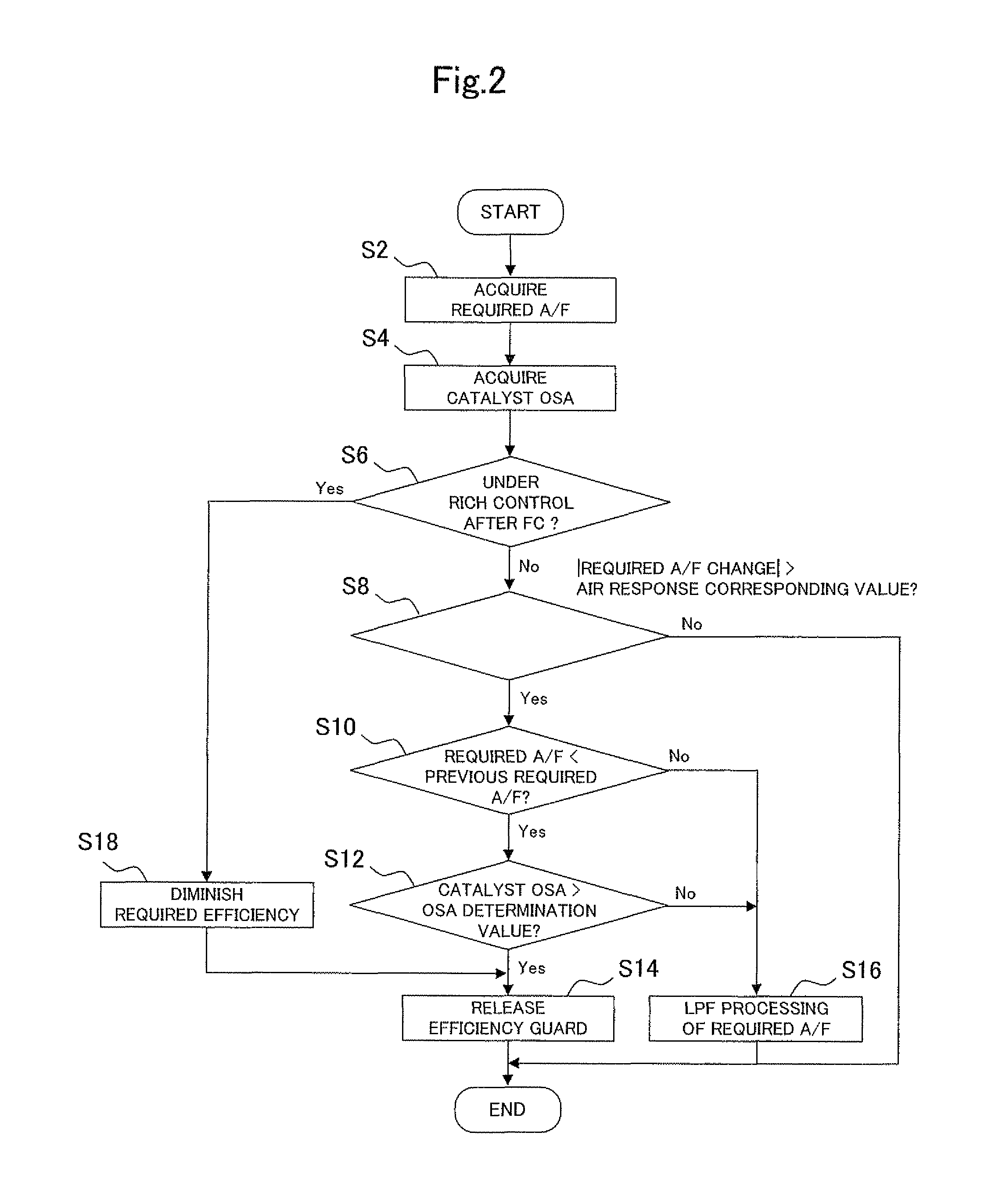
A control device for an internal combustion engine provided by the present invention is a control device which can satisfy a requirement concerning exhaust gas performance of the internal combustion engine, a requirement concerning fuel economy performance, and a requirement concerning operation performance with an excellent balance by properly regulating a change speed of a required air-fuel ratio and an ignition timing. The present control device keeps the ignition timing at an optimal ignition timing if a predetermined permission condition is not satisfied. However, when the permission condition is satisfied, the present control device controls the ignition timing so as to compensate for a difference which occurs between torque which is estimated from an operation of an actuator for air quantity control and required torque by the ignition timing. Further, if a predetermined lessening condition is not satisfied, the present control device determines an original required air-fuel ratio directly as a final required air-fuel ratio. However, if the lessening condition is satisfied, the present control device processes a signal of the original required air-fuel ratio to lessen a change speed thereof, and determines a required air-fuel ratio the change speed of which is lessened as a final required air-fuel ratio. The permission condition includes the required air-fuel ratio changing in a rich direction, and a change amount thereof being larger than a predetermined determination reference value, and the lessening condition includes the change amount of the required air-fuel ratio being larger than a determination reference value, and the permission condition being unsatisfied.

Description

TECHNICAL FIELD[0001]The present invention relates to a control device for an internal combustion engine, and particularly relates to a control device for an internal combustion engine which adopts torque and an air-fuel ratio as control variables.BACKGROUND ART[0002]As one of control methods of internal combustion engines, there is known a method which determines a manipulated variable of each actuator with torque and an air-fuel ratio as control variables. For example, Japanese Patent Laid-Open No. 2010-7489 discloses a method which determines a required torque and a required air-fuel ratio for an internal combustion engine, and determines respective manipulated variables of a throttle, an ignition device and a fuel injection device so as to realize them. With regard to a throttle, a throttle opening which is a manipulated variable thereof is determined in accordance with a target air quantity for realizing required torque. For example, with use of an inverse model of an air model...

Claims


Application Information

Patent Timeline
Patent Type & Authority Patents(United States)
IPC IPC(8): F02D43/04
CPCF02D2250/21F02D2041/1431F02D41/0002F02D37/02F02D41/1497F02D2200/1004F02D43/04F02D2200/0814F02D41/0295Y02T10/42Y02T10/40
Inventor OKAZAKI, SHUNTAROYOSHIZAKI, SATOSHISHIBAYAMA, MASASHISHOKATSU, KAORUKAWAKAMI, HAJIME
Owner TOYOTA JIDOSHA KK
Learn More