
Torque sensor

a technology of torque sensor and axial length, which is applied in the direction of force measurement, electric/magnetic measurement arrangement, instruments, etc., can solve the problems of difficult design of conventional torque sensor using a torsion mechanism, complicated structure accordingly, and difficulty in designing conventional torque sensor with a short axial length. , to achieve the effect of reducing the cost of space, improving the detection accuracy, and high accuracy

Active Publication Date: 2014-03-11
TRI FORCE MANAGEMENT CORP
View PDF26 Cites 16 Cited by
  • Summary
  • Abstract
  • Description
  • Claims
  • Application Information

AI Technical Summary

Benefits of technology

[0126]The annular deformation body, the left side support body, and the right side support body can be constructed by flat structures having small axial thicknesses, which thus allows setting the axial length of the whole sensor short. Moreover, because torque detection is performed based on a distortion in the shape of the annular deformation body, it is necessary to use as the annular deformation body a material that produces elastic deformation, but even by using a material having a relatively high rigidity, high accuracy detection can be performed. Further, because a distortion in the shape of the annular deformation body can be detected by a capacitive element composed of a pair of electrodes, the structure is also simplified, which can contribute to a reduction in cost.
[0133]Moreover, when the configuration of integrating two annular deformation bodies disposed at the outside and inside is adopted, in place of a capacitive element composed of a displacement electrode and a fixed electrode, a capacitive element composed of an outer displacement electrode formed on the inner peripheral surface of the outer annular deformation body and an inner displacement electrode formed on the outer peripheral surface of the inner annular deformation body can also be formed. Also in this case, by using circular annular structures as both annular deformation bodies so that both are deformed into elliptical shapes when torque is exerted and providing connection points shifted by 90 degrees from each other so that the long-axis direction of one ellipse serves as the short-axis direction of the other ellipse, the amount of variation in the electrode interval between the outer displacement electrode and the inner displacement electrode can be set large, and the detection sensitivity can be further improved.

Problems solved by technology

However, it is difficult to design the conventional type of torque sensor using a torsion bar with a short axial length.
But, provision of such a mechanism complicates the structure accordingly, which is not preferable.
Ultimately, it is inevitable to set the overall length of the torsion bar so long that a change in axial length can be disregarded, so that it is difficult to design the conventional torque sensor with a short axial length.
Therefore, as an object in which torsion is produced, of course, a perfectly rigid body cannot be used, and it is necessary to use a structure that produces some extent of elastic deformation.
However, if a torsion angle produced as a result of torque detection is large, frequency characteristics of a control system deteriorate due to the hunting phenomenon, and high-speed response can no longer be secured.
However, with the conventionally proposed magnetic methods for detecting torsion angles, it is difficult to detect a small torsion angle at high accuracy.
However, in the conventionally proposed torque sensors, it is necessary to adhere a strain gauge to a torsion bar, form a magneto-strictive film, or attach magnets or coils, so that the structure is inevitably considerably complicated.

Method used


Image

  • Torque sensor
  • Torque sensor
  • Torque sensor

Examples


Embodiment Construction

[0178]Hereinafter, the present invention will be described based on illustrated embodiments.

>>

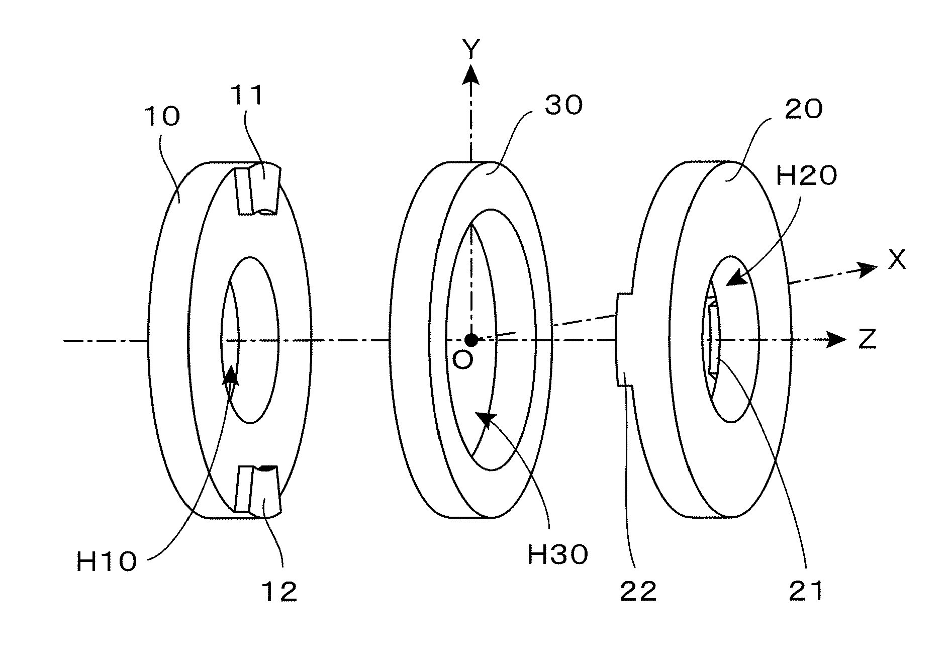
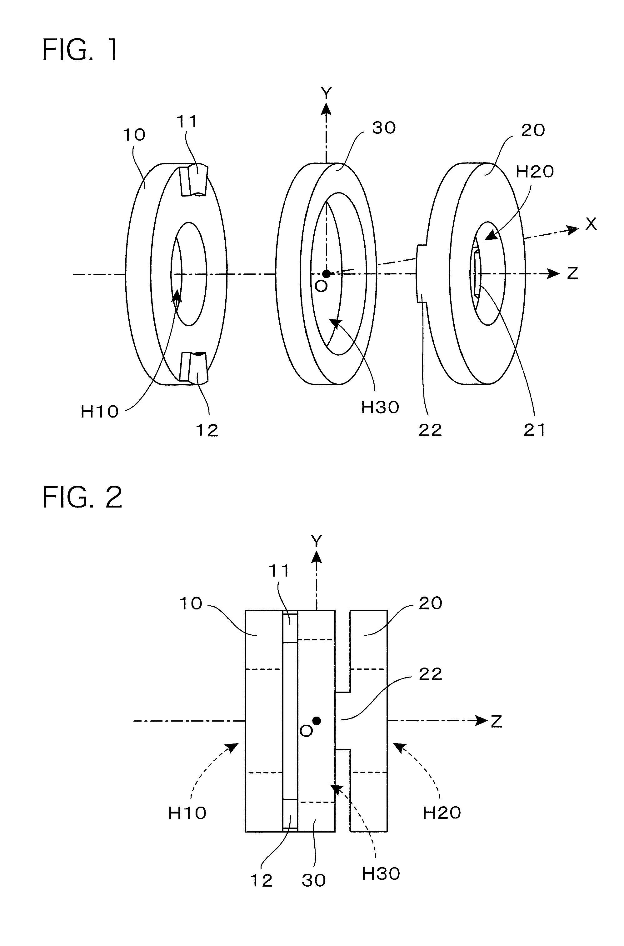
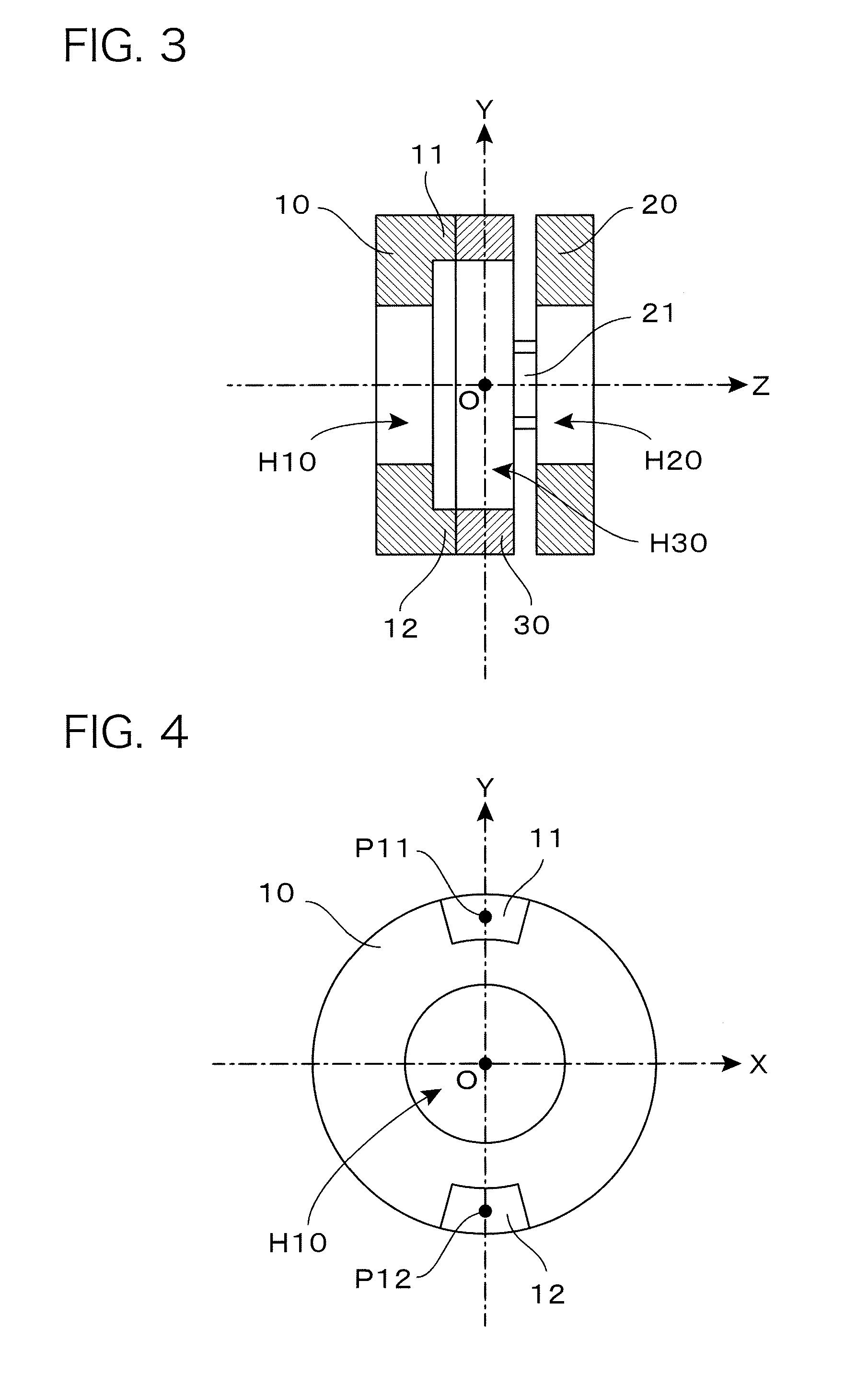
[0179]FIG. 1 is an exploded perspective view of a basic structural section of a torque sensor according to a basic embodiment of the present invention. As illustrated, the basic structural section is constructed by disposing an annular deformation body 30 between a left side support body 10 and a right side support body 20 and joining the three structural elements to each other. Here, for the sake of convenience, an XYZ three-dimensional coordinate system is defined as illustrated to give the following description. Here, the Z-axis drawn in the horizontal direction of the figure corresponds to a rotation axis of torque to be detected, and the torque sensor fulfills a function of detecting torque about the rotation axis (about the Z-axis).

[0180]The annular deformation body 30 disposed at the middle of the figure is made of a material that produces elastic deformation clue to exertion of torq...


PUM

PropertyMeasurementUnit
torqueaaaaaaaaaa
elastic deformationaaaaaaaaaa
capacitanceaaaaaaaaaa

Abstract

A small, high-stiffness torque sensor. An annular deformable body is disposed between left and right side supports. Convex sections protruding from the left side support in a rightward direction are joined to the left side surface of the annular deformable body, and convex sections protruding from the right side support in a leftward direction are joined to the right side surface of the annular deformable body. When force is applied to the right side support and torque around the Z axis acts on the left side support, the annular deformable body is elliptically deformed and the long-axis position of the inner peripheral surface of the annular deformable body moves away from the Z axis while the short-axis position moves closer to the Z axis. The acting torque is detected as a variation in the capacitance value of capacitive elements formed by displacement electrodes and fixed electrodes.

Description

RELATED APPLICATION INFORMATION[0001]This application is a 371 of International Application PCT / JP2011 / 067713 filed 27 Jul. 2011 Entitled “Torque Sensor”, which was published on 09 Feb. 2012, with International Publication Number WO 2012 / 018031 A1, and which claims priority from is incorporated herein by reference.TECHNICAL FIELD[0002]The present invention relates to a torque sensor, and particularly, to a sensor having a function of outputting torque exerted about a predetermined rotation axis as an electrical signal.BACKGROUND ART[0003]Torque sensors for detecting torque exerted about a predetermined rotation axis have been widely used for a variety of transport machinery and industrial machinery. For example, Japanese Unexamined Patent Publication No. 2009-058388 discloses a torque sensor of a type in which mechanical deformation caused by exertion of torque is detected by a strain gauge. Moreover, Japanese Unexamined Patent Publication No. 2007-024641 discloses a sensor for dete...

Claims


Application Information

Patent Timeline
Patent Type & Authority Patents(United States)
IPC IPC(8): G01L3/02
CPCG01L3/10G01L3/106
Inventor NISHIOKI, NOBUHISAOKADA, KAZUHIRO
Owner TRI FORCE MANAGEMENT CORP
Learn More