Method of manufacturing hollow composite parts with in situ formed internal structures

a composite and in situ technology, applied in the field of composite manufacturing complex structures, can solve the problems of parts not being usable, parts not being infused completely or uniformly into the inner cavity or the shear cavity, and parts not being infused completely or uniformly, and achieve the effect of convenient disassembly

Inactive Publication Date: 2014-03-11
GUITTON MAURICE
View PDF14 Cites 13 Cited by
  • Summary
  • Abstract
  • Description
  • Claims
  • Application Information

AI Technical Summary

Benefits of technology

[0017]In the drawings, the part is a wind turbine blade or mast with at least one internal support structure, hereinafter known as a shear spar. The shear spar is formed by laying up composite laminated layers around a removable mandrel temporarily assembled inside the mold cavity and at the desired location. The removable mandrel includes two parallel jig plate assemblies spaced apart inside the part's internal cavity. In the embodiment described herein, the part is made of laminate material can be made by resin infusion, pre-preg, film infusion or with thermoplastic material with long fibers reinforcement. Composite laminate material is laid up over the inner cavity and inbetween the two jig plates forming an I-shaped uncured laminated structure. A thin twisted UD tow of fiber or a thin breaded rope fiber ribbon of composite material, called a noodle or filler, may be placed in the shear web to eliminate voids that can be created that lead to internal delimitation on the top and bottom of the laminated structure.
[0018]Each jig plate assembly is made up of at least three conical jig plates stacked in an edge-to-edge manner inside the part's inner cavity. The middle plate includes upper and lower straight edges that converge towards the opposite closed end of the part. During assembly and disassembly, the middle jig plate slides freely inward or outward between the upper and lower jig plates thereby enabling the jib plate assembly to selectively expand or collapse, respectively.
[0019]A key component of the invention is the envelope discussed above used with the two jib plate assemblies. Once layup is completed, the top section of the mold is then closed over the lower section of the mold. The inner cavity is then evacuated and the cure cycle is started generating heat according the resin system cycle of the material supplier. As stated above, the air inside the envelope may be progressively replaced by air or nitrogen gas thereby gradually inflating the envelope and uniformly compacting the laminate layers. This process is monitored. The air or the nitrogen gas causes the envelope to expand evenly and uniformly to compress the laminate layers in all directions. After the composite laminated layers have cured, the part is removed from the mold and the elastomeric envelope is opened thereby enabling it to compress and shirk so that it may be removed from the part's inner cavity. The middle plate on each jig plate is able to can slide longitudinally in between the upper and lower jig plates enabling the entire mandrel to be easily removed from the part.

Problems solved by technology

One drawback with the method disclosed in U.S. Pat. No. 7,473,385 is that liquid resin is not infused completely or uniformly into the inner cavity or the shear cavity.
As a result, defects in the part may occur that make the part unusable.
Another drawback with this method is that it requires the use two different manufacturing processes—heat / vacuum compaction process and vacuum resin infusion process.
The use of these two processes make setup and teardown time longer and more difficult.

Method used


Image

  • Method of manufacturing hollow composite parts with in situ formed internal structures
  • Method of manufacturing hollow composite parts with in situ formed internal structures
  • Method of manufacturing hollow composite parts with in situ formed internal structures

Examples


Embodiment Construction

)

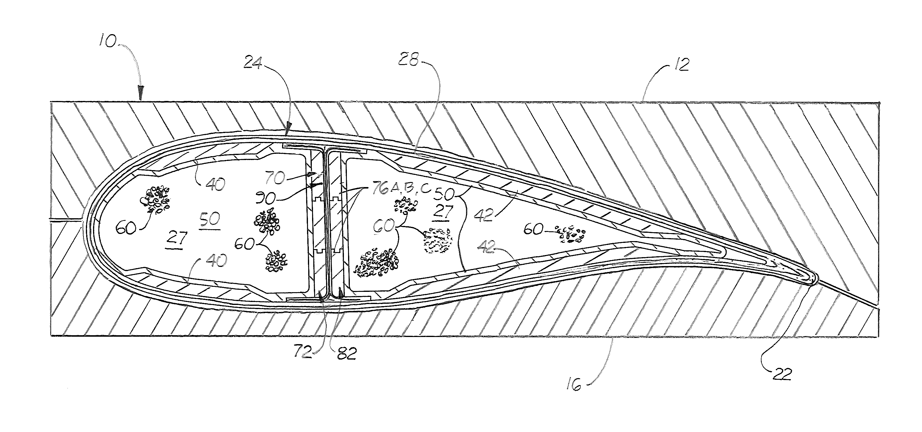
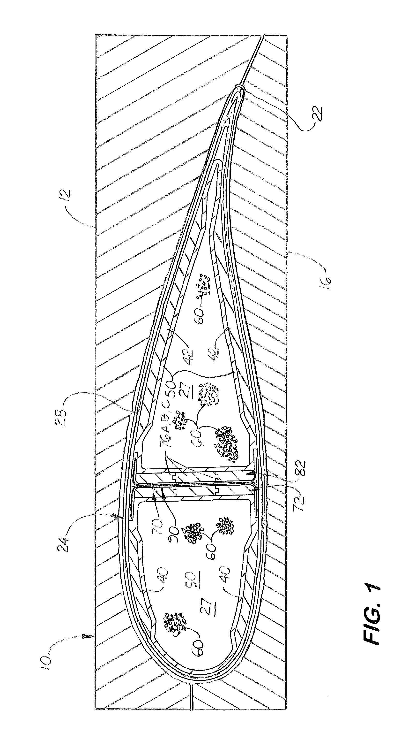
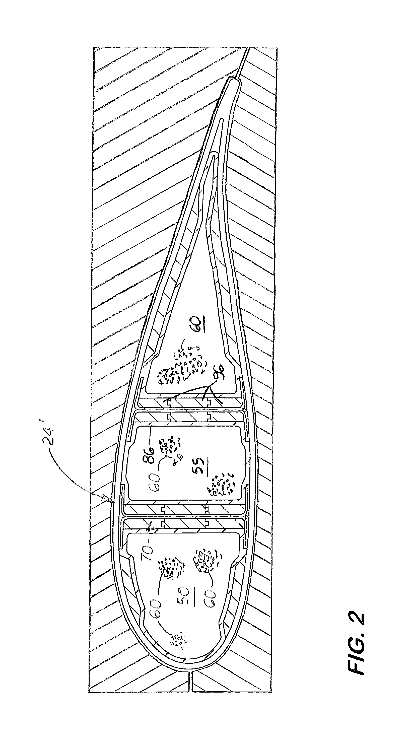
[0026]Disclosed here in a method for manufacturing a complex shape in situ, hollow core composite blade or boat mast part 24 with at least one internal structure, called a shear spar 30 formed in situ the part's inner cavity 27 and simultaneously with the part's outer side walls 28. As shown in FIGS. 3 and 4, the part 24, 24′ is shown for illustration to be a wind turbine blade. It should be understood that the method disclosed may be used to manufacture other complex, hollow structures, such as a mast, a pole, and an aircraft wing or stabilizer made of composite material.

[0027]The method disclosed uses the elastomeric bladder, called an envelope 50 that is taught in U.S. patent application Ser. No. 12 / 296,689, filed on Jun. 3, 2009, and now incorporated by reference herein. The envelope 50 is made from an elastomeric material and filled with a plurality of non-inactivity, free flowing spherical objects 60 of different or identical diameters. The envelope 50, the shape of which is ...


PUM

PropertyMeasurementUnit
structureaaaaaaaaaa
forceaaaaaaaaaa
structuresaaaaaaaaaa

Abstract

A method for manufacturing complex hollow composite parts with at least one internal structure formed in situ by laying laminated layers around a removable mandrel assembled inside the part's inner cavity. The inner mandrel is made up of two jig plate assemblies aligned in a parallel manner and space apart where the internal structure is to manufactured. Each jig plate assembly is made up of at least three jig plates stacked in an edge-to-edge manner Located on opposite sides of each jig plate assembly is an elastic envelope filled with spherical objects. When evacuated, the envelope collapses and relaxes and composite material may then laid up inside the inner cavity and around the envelopes. When exposed to a heat, the envelopes expand and in situ and form internal structures inside surface of the cavity. Each envelope and each jig plate assemblies can be easily dissembled and reused.

Description

[0001]This utility patent application is based on and claims the priority filing date of U.S. Provisional patent application 61 / 467,871 filed on Mar. 25, 2011.BACKGROUND OF THE INVENTION[0002]1. Field of the Invention[0003]The disclosed embodiments relate to the field of manufacturing complex structures made of composites that are formed in molds using compacting molding processes , and more particularly, to such structures that are hollow and include internal structures.[0004]2. Description of the Related Art[0005]The inventor is a co-inventor of a method of producing structures of complex shapes of composite materials disclosed in U.S. patent application Ser. No. 12 / 296,689, filed on Jun. 3, 2009. The method discloses the use of a flexible, elastomeric envelope, also called a bladder, filled with small spherical objects of different diameters that after undergoing evacuation of air, form a rigid mandrel for laying up dry fiber, prepreg, or film resin to create composite laminated ...

Claims


Application Information

Patent Timeline
Patent Type & Authority Patents(United States)
IPC IPC(8): B28B7/28
CPCB29C70/46B29C33/485B29L2031/766B29L2031/085B29C70/44B29C70/68Y02P70/50
Inventor GUITTON, MAURICE
Owner GUITTON MAURICE
Why Eureka
Try Eureka