Method for producing semiconductor device and semiconductor device having pillar-shaped semiconductor
a semiconductor and pillar-shaped technology, applied in semiconductor/solid-state device manufacturing, semiconductor devices, electrical equipment, etc., can solve the problems of difficult to stop etching with good controllability and difficult to form a thick mask layer, and achieve high integration, stable operation of a semiconductor device, and high-speed driving
- Summary
- Abstract
- Description
- Claims
- Application Information
AI Technical Summary
Benefits of technology
Problems solved by technology
Method used
Image
Examples
first embodiment
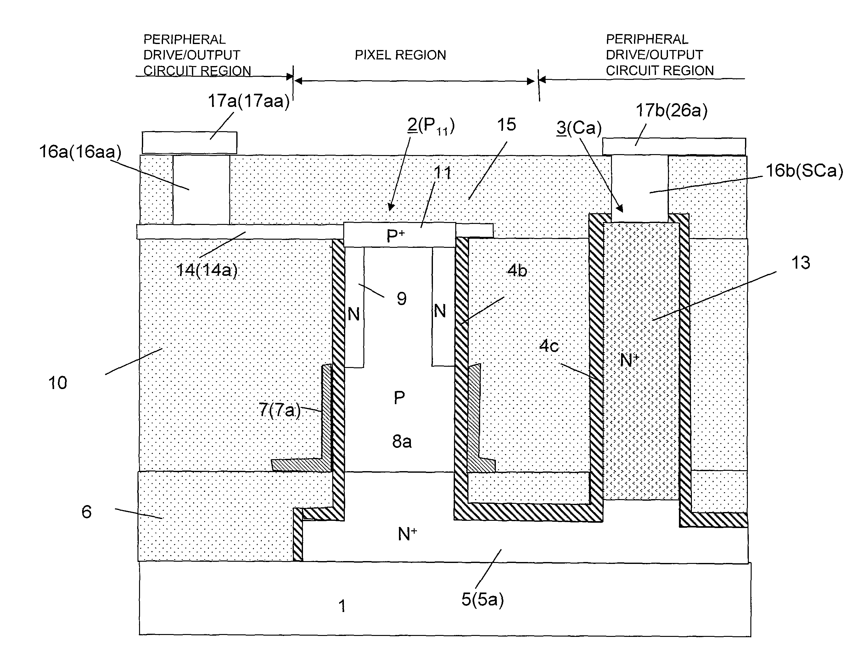
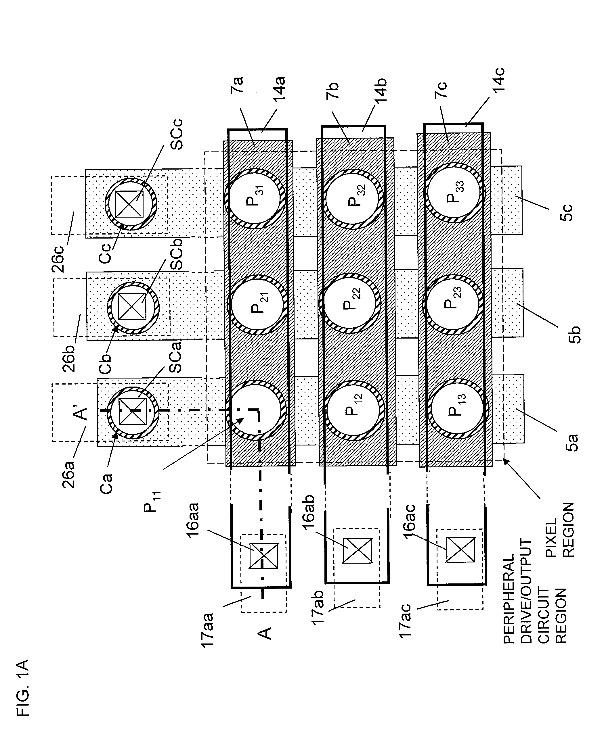
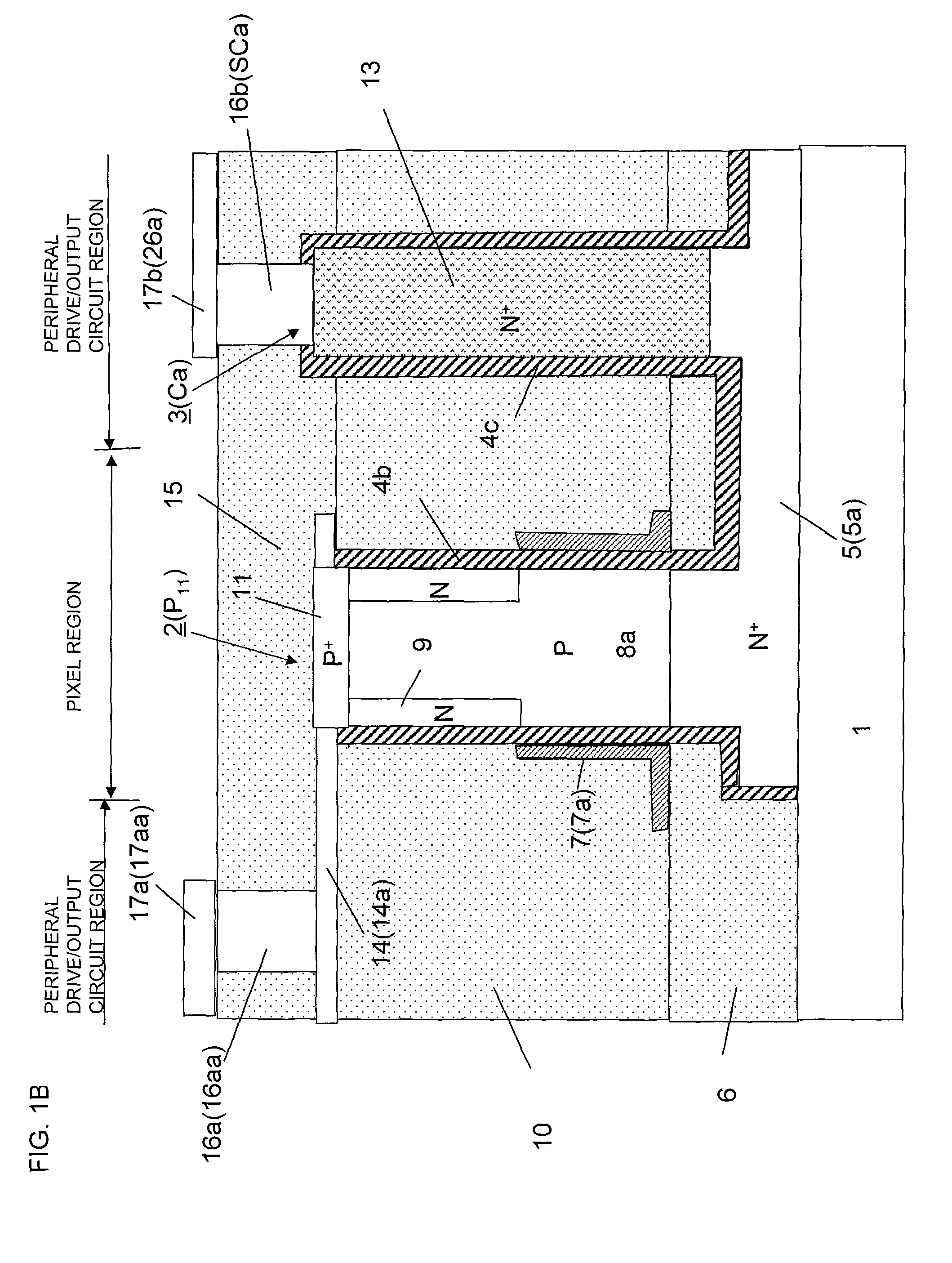
[0099]A solid-state imaging device according a first embodiment of the present invention, and a method for producing the solid-state imaging device will now be described with reference to FIGS. 1A, 1B, and 2A to 2F.
[0100]FIG. 1A is a plan view of a solid-state imaging device according to this embodiment. In a pixel region of the solid-state imaging device, silicon pillars P11 to P33 that form pixels are arranged in a vertical (column) direction and a horizontal (row) direction two-dimensionally (in a matrix). These silicon pillars P11 to P33 are formed on signal line N+ layers 5a, 5b, and 5c that are formed on a silicon oxide substrate 1 and that extend in the vertical (column) direction of the figure and to a peripheral drive / output circuit region. The signal line N+ layers 5a, 5b, and 5c are respectively connected to signal line metal layers 26a, 26b, and 26c through contact holes SCa, SCb, and SCc that are respectively formed on second silicon pillars Ca, Cb, and Cc in the periph...
second embodiment
[0114]FIGS. 3A to 3C illustrate a method for producing a solid-state imaging device according to this embodiment. In this embodiment, the electrical resistance between a signal line N+ layer 5 and a signal line metal layer 17b is decreased by forming a silicide layer 23 instead of the conductor N+ layer 13 of the second silicon pillar 3 that establishes contact in FIG. 1B.
[0115]In this embodiment, first, the steps illustrated in FIGS. 2A to 2D in the first embodiment are performed. Subsequently, as illustrated in FIG. 3A, a pixel selection line conductor layer 14 connected to a P+ layer 11 of a first silicon pillar 2 is formed. A SiO2 layer 18 and a photoresist layer 19 are formed by CVD, and a through-hole 20 is formed on a second silicon pillar 3 by photolithography and etching. Subsequently, as illustrated in FIG. 3A, an impurity such as silicon (Si) or hydrogen (H), which does not function as a donor or an acceptor, is introduced into the second silicon pillar 3 by ion implantat...
third embodiment
[0119]A method for producing a solid-state imaging device according to this embodiment will now be described with reference to FIGS. 4A to 4D and FIG. 5. In this embodiment, the resistance between a signal line N+ layer 5 and a signal line metal layer 73b is decreased by forming a metal layer 70a or 70b composed of tungsten (W), copper (Cu), or the like instead of the conductor N+ layer 13 of the second silicon pillar 3 that establishes contact in FIG. 1B.
[0120]In this embodiment, first, the steps illustrated in FIGS. 2A to 2C in the first embodiment are performed. Subsequently, as illustrated in FIG. 4A, an N layer 9 that forms a photodiode is formed on an outer peripheral portion of a first silicon pillar 2. A Si nitride (SiN) layer 64 is formed on the first silicon pillar 2, a second silicon pillar 3, and a SiO2 layer 6 by CVD. Subsequently, as illustrated in FIG. 4A, the whole structure is covered with a SiO2 layer 65, and the surface of the SiO2 layer 65 is polished by chemical...
PUM
 Abstract
Description
Claims
Application Information
 - R&D
- Intellectual Property
- Life Sciences
- Materials
- Tech Scout
- Unparalleled Data Quality
- Higher Quality Content
- 60% Fewer Hallucinations
Browse by: Latest US Patents, China's latest patents, Technical Efficacy Thesaurus, Application Domain, Technology Topic, Popular Technical Reports.
© 2025 PatSnap. All rights reserved.Legal|Privacy policy|Modern Slavery Act Transparency Statement|Sitemap|About US| Contact US: help@patsnap.com


