Structural insulating core for concrete walls and floors

a technology of structural insulation core and concrete wall, which is applied in the direction of walls, joists, girders, etc., can solve the problems of no framing system in conjunction with rigid insulation core, no lanahan patent uses its panels to form concrete columns or beams, etc., to improve joint connection, reduce bending stress, and increase concrete strength

Inactive Publication Date: 2014-03-18
LEBLANG DENNIS WILLIAM
View PDF34 Cites 8 Cited by
  • Summary
  • Abstract
  • Description
  • Claims
  • Application Information

AI Technical Summary

Benefits of technology

[0027]A wall mold for bonding concrete to a structural insulating core of horizontal and vertical interlocking tongue and groove spacer blocks (shown using foam spacers or spacer insulation) between support channels with concrete bonded to the spacer blocks, connectors and support channels. The spacer blocks can have indentations and recesses to form many other molds by using columns, ribs, beams, projections, and recesses that add strength or molds that drain water from between the concrete and spacer blocks. The spacer blocks can cover the flanges of the support channels or just protrude beyond the support channels to form a thermal break.
[0028]Another variation of the invention is the flexibility of the spacer blocks to be wider than the support channels to overlap the flanges of the support channels in various different ways. The spacer blocks interlock vertically with a tongue and groove connections between the support channels. When the spacer blocks are wider than the support channels a portion of the spacer block or projection extends over the flange of the support channels. The projections of a spacer block can be longer than the flange of the support channels and a recess is formed on the adjacent spacer block providing a better joint connection between spacer blocks. The projections on the spacer blocks can be located on the groove side of the spacer blocks or on the tongue side of the spacer block allowing the tongue to fit between the lips and flange of the support channels. Horizontal bracing channels can also be inserted through the holes of the support channels allowing mechanical items to pass through the holes in the support channels.
[0029]Another variation of the invention is when the concrete wall panel needs to be a larger size, the support members need to be stronger and deeper to reduce the bending stress on the concrete when being erected. For example, vertical and horizontal rib molds may be added as headers and cripple supports for doors and windows. In addition, beam or column molds within the spacer blocks may be installed to increase the strength of the concrete of the wall panel. The larger column and beam molds can be installed in the foam spacers to support additional vertical and horizontal dead and live loads exerted on the concrete wall panels. Beams and columns are cut into the structural insulating core and laid horizontally into a forming bead where concrete is poured over or under the structural insulating core. When the concrete on the wall panel is thinner, the drainage channels that protrude from the spacer blocks or the recessed grooves that indent the spacer blocks may be used to increase the strength of the wall panel. Both of the drainage channels or recessed grooves can also create an air space to allow water to drain from behind the concrete or be used as architectural accents depending on the thickness of the concrete.

Problems solved by technology

None of the patents have a framing system in conjunction with a rigid insulation core.
None of the Lanahan patents use their panels to form concrete columns or beams.

Method used


Image

  • Structural insulating core for concrete walls and floors
  • Structural insulating core for concrete walls and floors
  • Structural insulating core for concrete walls and floors

Examples


Embodiment Construction

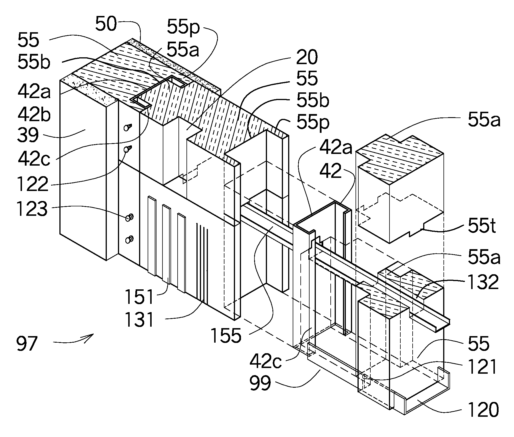
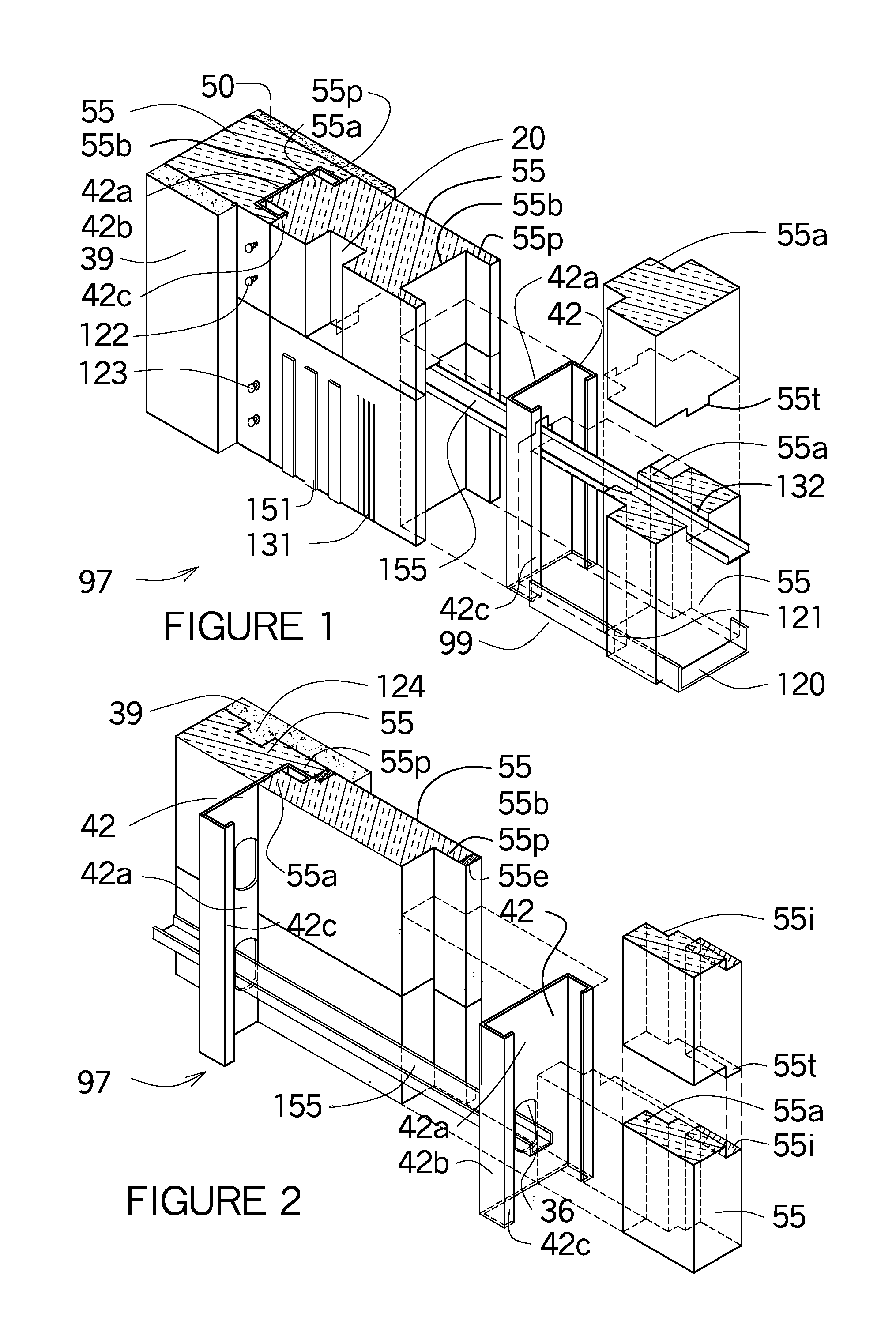
[0077]FIG. 1 shows an isometric view a wall mold 97 with the structural insulating core 111 shown in a vertical position, however the wall mold 97 is built in a horizontal position and erected vertically after concrete 39 is install. The support channels in the structural insulating core 111 are shown as C channels 42 and foam spacers 55 fit between the C channels 42. The left side shows the wall assembled and the right side shows the various wall components separated. The right side shows the support channel as a C channel 42 with the horizontal bracing channel 150 shown as a horizontal U channel 155 passing through the hole 36 in the web 42a of the C channel 42. On both sides of the C channel 42 are foam spacers 55 that have a trough 132 at the top of each foam spacers 55. The horizontal U channel 155 fits through the hole 36 and into the troughs 132 of the foam spacers 55. Another foam spacers 55 is shown above the horizontal U channel 155 where a horizontal tongue 55t fits into ...


PUM


Abstract

A concrete wall mold formed with a structural insulating core of horizontally and vertically integrated spacer blocks with tongue and groove connections between framing members having connectors attached to the framing members and embedded into the concrete surface. The spacer blocks having additional support molds to reinforce the concrete surface by means of adding rib, column, beam molds or drainage channels and recess grooves. The concrete surface may be located above or below the concrete wall mold.

Description

REFERENCE TO RELATED APPLICATIONS[0001]This application is a continuation-in-part of patent application Ser. No. 12 / 456,707 filed Jun. 22, 2009 now U.S. Pat. No. 8,161,699 and Ser. No. 12 / 231,875 filed on Sep. 8, 2008 now U.S. Pat. No. 8,176,696.FEDERALLY SPONSORED RESEARCH OR DEVELOPMENT[0002]Not Applicable.PARTIES OR JOINT RESEARCH[0003]Not Applicable.FIELD OF THE INVENTION[0004]A concrete wall mold having an insulated foam core of foam spacers that interlock vertically and horizontally with tongue and groove connections between framing members having connectors embedded into the concrete facing. Additional drainage channels, recessed grooves, rib molds, column molds or beam molds can be formed within the foam spacers for additional strength or bonding between the concrete facing and the foam spacers whether concrete in installed above or below the foam spacers prior to being erected in a vertical position.BACKGROUND OF THE INVENTION[0005]A precast concrete wall is very difficult ...

Claims


Application Information

Patent Timeline
Patent Type & Authority Patents(United States)
IPC IPC(8): E04C1/42
CPCE04C2003/0473E04B1/14E04C3/09
Inventor LEBLANG, DENNIS, WILLIAM
Owner LEBLANG DENNIS WILLIAM
Why Eureka
Try Eureka