Roofing tile fastening system

a technology for fastening systems and roofs, which is applied in the field of roofing tile fastening systems, can solve the problems of reducing the installation cost, affecting the installation efficiency of roofs, so as to reduce waste, accelerate the installation of slate roofs, and reduce the effect of was

Active Publication Date: 2014-03-25
WILLIAMS JOHN M +1
View PDF9 Cites 6 Cited by
  • Summary
  • Abstract
  • Description
  • Claims
  • Application Information

AI Technical Summary

Benefits of technology

[0003]The present disclosure provides a method and system which not only satisfies the needs noted above, but also facilitates and expedites the installation of slate roofs by roofers having no prior experience with slate roof installation. These ends are achieved with installation strips that can be installed quickly and easily by hand (hammer and nail) or by mechanically assisted means such as by a nail gun.
[0004]Previously, a slate roofer required a “feel” for applying the proper amount of hammer driving force needed to properly install a slate shingle by hammer and nail. This “feel” is no longer required with the slate installation system described herein. In one embodiment, other than along the border of a roof, an installer can pound installation nails as hard as possible without causing damage to the slate roofing tiles. This reduces waste, eliminates scrapped and damaged tiles due to installation damage, reduces material costs by reducing the number of tiles required and reduces installation time, all while potentially using lower cost roofing labor.

Problems solved by technology

Unfortunately, there is a scarcity of experienced slate roofers.
This scarcity has led to hesitancy on the part of some architects and home builders to specify and install slate roofs, knowing that there are few craftsmen available to properly install slate roofs.
Moreover, the scarcity of qualified skilled slate roofers has driven up the installation cost.

Method used


Image

  • Roofing tile fastening system
  • Roofing tile fastening system
  • Roofing tile fastening system

Examples


Embodiment Construction

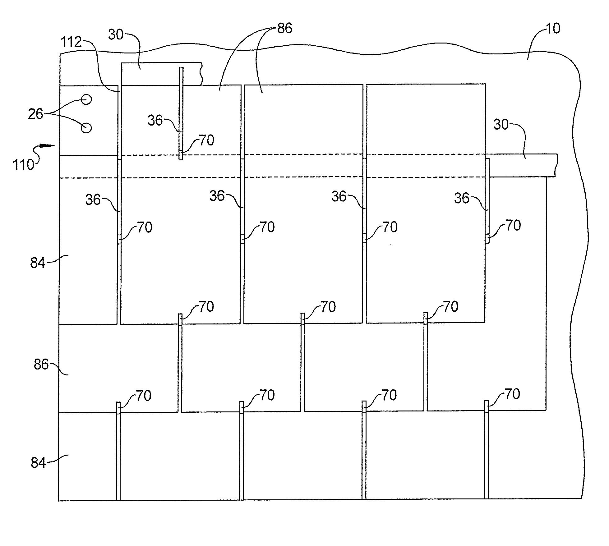
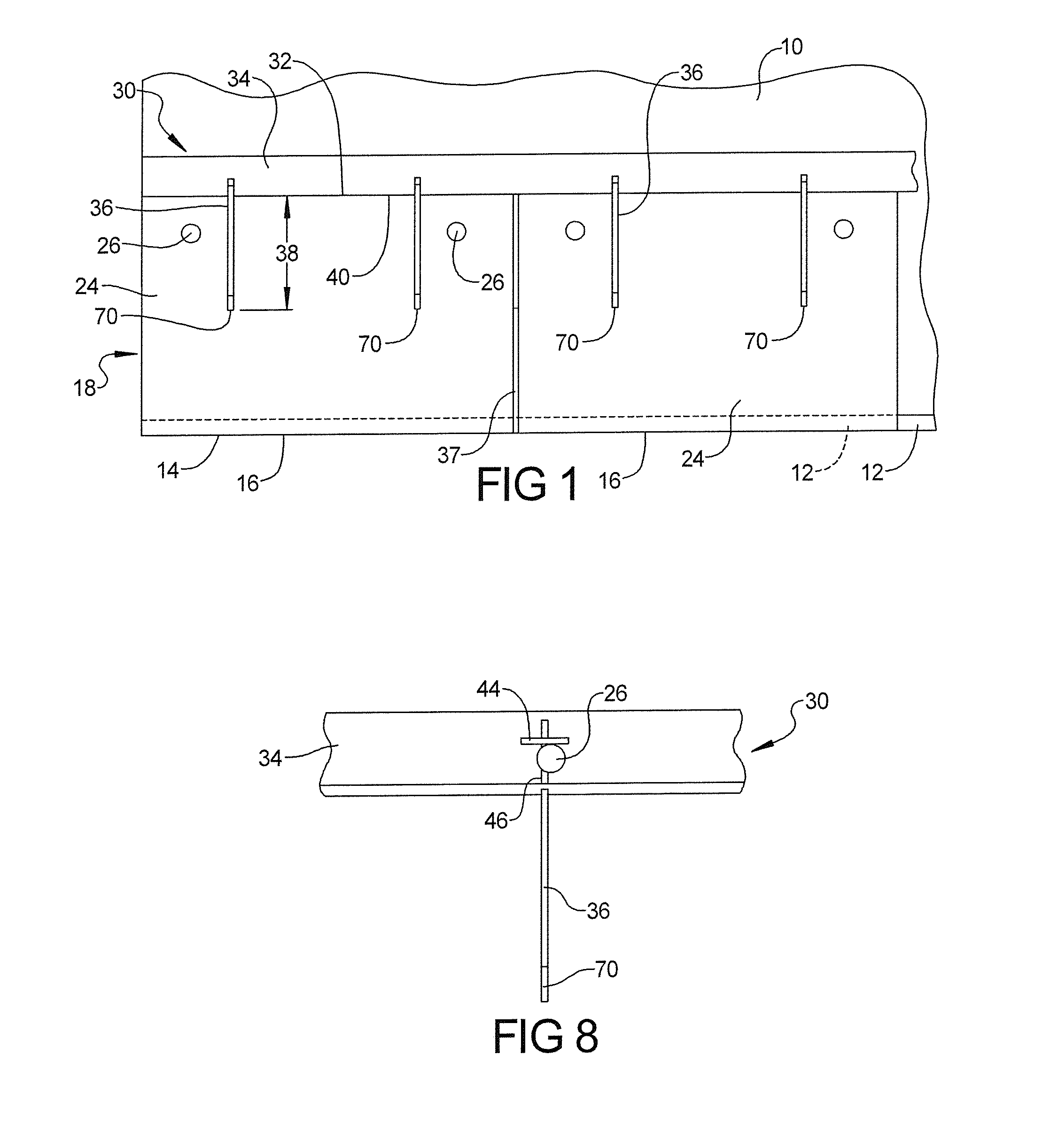
[0035]As seen in FIG. 1, the installation of a slate roof in accordance with this disclosure begins at the bottom edge or eve of a conventional roof 10, typically constructed of plywood sheets. To begin installation, a small wooden strip 12 (FIGS. 1 and 7), referred to as a cant strip, is nailed or otherwise attached to the lower edge 14 of roof 10. Cant strip 12 provides the initial elevation and spacing to the lower edge 16 of a first row 18 of slate tiles so as to match the angle or rise of the subsequent rows of slate tiles, as seen in FIG. 7.

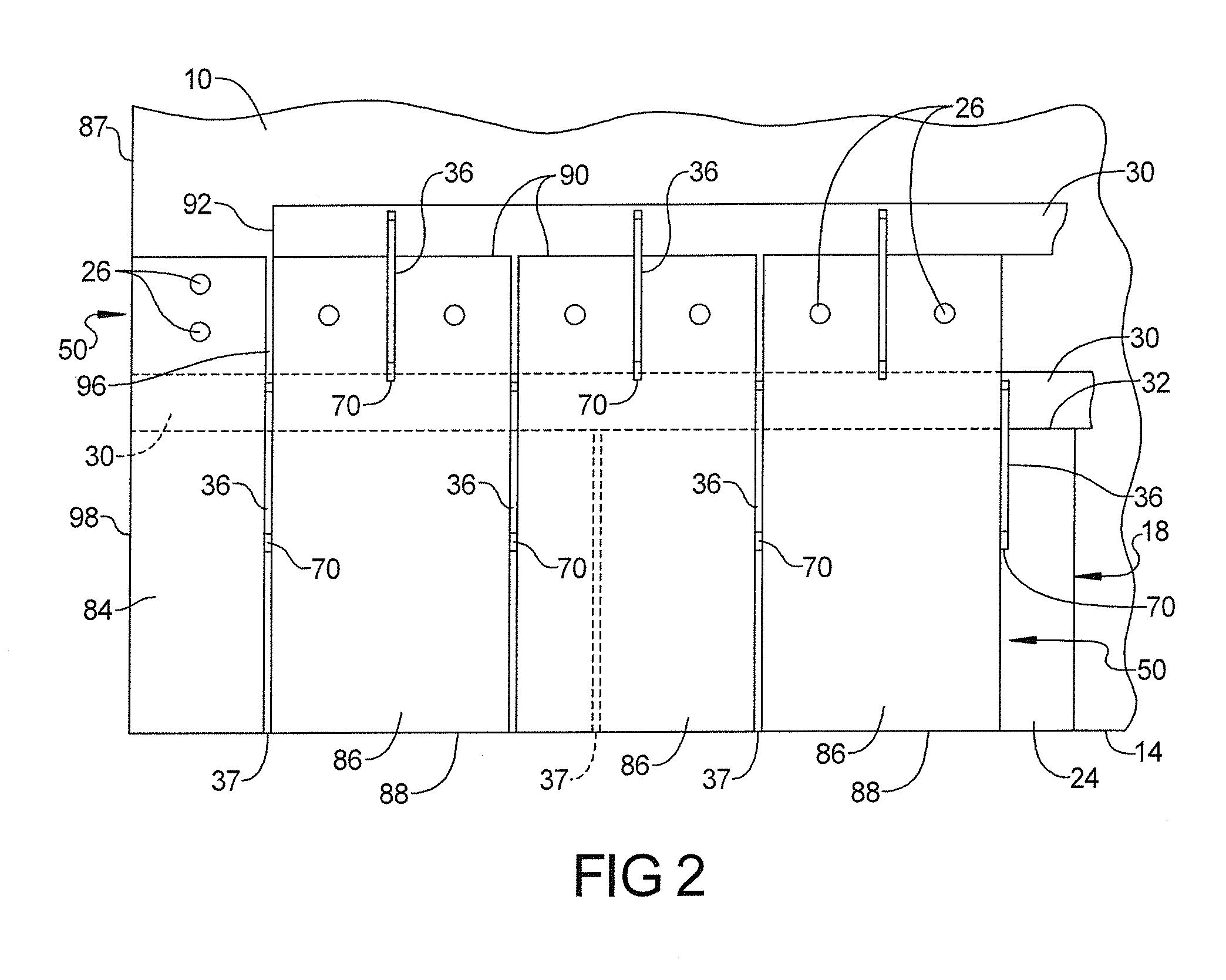
[0036]After the cant strip 12 is installed, the bottom or first row 18 of slate eve tiles 24 is installed by conventional means, such as by hammer and nail. Tiles 24 are provided with punched holes for receiving copper or stainless steel roofing nails 26. Once the first row 18 of slate tiles is installed, an installation strip assembly 30 is securely butted against the top edge 32 of the first row 18 of slate tiles 24, as seen in FIG. 1. As...


PUM


Abstract

A roofing tile installation system includes spaced rows of installation strips each having an elongated base to which is attached a plurality of spaced apart hooks. The hooks are formed with a profile that engages and presses on underlying tiles and that grips and hooks around the lower edge of an overlying tile. Each tile is positioned and held laterally between a pair of hooks and held vertically on the slope of a roof by a single hook. An improved weatherproofing system includes a second layer of water resistive material which protects an underlying layer of plastic weatherproofing material against exposure to sunlight and erosion from wind and rain.

Description

BACKGROUND AND SUMMARY[0001]Slate roofs are highly desirable from both an aesthetic and a functional viewpoint. The proper installation of a slate roof requires a skilled and experienced slate roofer. Unfortunately, there is a scarcity of experienced slate roofers. This scarcity has led to hesitancy on the part of some architects and home builders to specify and install slate roofs, knowing that there are few craftsmen available to properly install slate roofs. Moreover, the scarcity of qualified skilled slate roofers has driven up the installation cost.[0002]A need therefore exists for a method and system for installing slate roofs which do not require experienced slate roofers, and which can be practiced by virtually any roofer with a minimal amount of instruction.[0003]The present disclosure provides a method and system which not only satisfies the needs noted above, but also facilitates and expedites the installation of slate roofs by roofers having no prior experience with slat...

Claims


Application Information

Patent Timeline
Patent Type & Authority Patents(United States)
IPC IPC(8): E04D1/34
CPCE04D1/14E04D2001/3458E04D2001/3473E04D2001/345E04D1/34E04D2001/3447E04D2001/3411E04D2001/3482E04D2001/3438
Inventor WILLIAMS, JOHN M.WILLIAMS, ROBERT B.
Owner WILLIAMS JOHN M
Why Eureka
Try Eureka