Optical connector

a technology of optical connectors and connectors, applied in the field of optical connectors, can solve the problems of becoming unnecessary to clean the connectors, and achieve the effects of reducing the production of powder caused by the friction generated when the guide pins are inserted and fitted into the guide holes, stable connection performance, and no increase in connection loss

Active Publication Date: 2014-03-25
JAPAN AVIATION ELECTRONICS IND LTD
View PDF12 Cites 8 Cited by
  • Summary
  • Abstract
  • Description
  • Claims
  • Application Information

AI Technical Summary

Benefits of technology

[0023]In consideration of the above described problems, an object of the present invention is to provide optical connectors capable of greatly reducing powder caused by the friction generated when guide pins are inserted and fitted into the guide holes, thereby preventing connection loss from increasing even if frequent connection and disconnection are performed and also allowing cleaning to be eliminated.
[0025]According to the present invention, the production of powder caused by the friction generated when the guide pins are inserted and fitted into the guide holes is greatly reduced. Connection loss does not increase (worsen) even when frequent connection and disconnection are performed, providing stable connection performance. In addition, it becomes unnecessary to clean the connector.

Problems solved by technology

In addition, it becomes unnecessary to clean the connector.

Method used


Image

  • Optical connector
  • Optical connector
  • Optical connector

Examples


Embodiment Construction

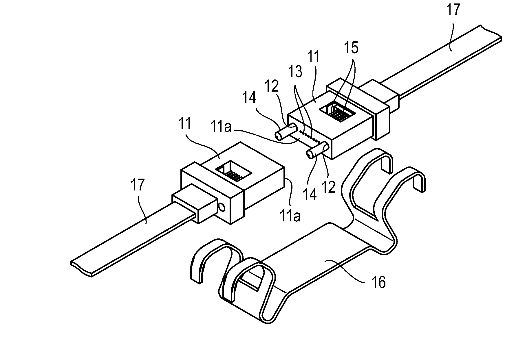
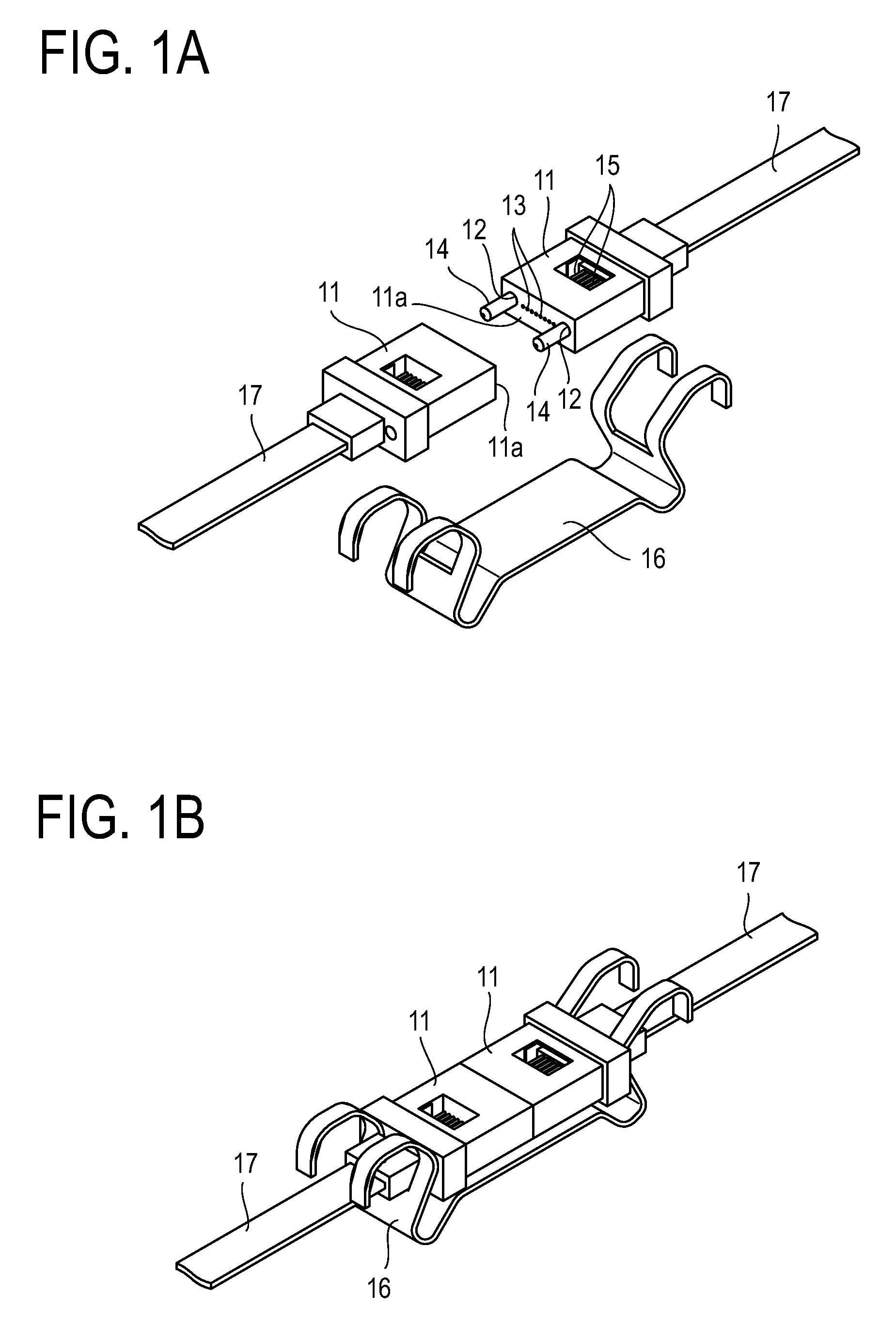
[0034]In the present invention, end faces of a pair of ferrules that hold multiple multimode optical fibers (core diameter: 50 μm) are positioned with two guide pins and butted against each other to connect the optical fibers held by the pair of ferrules in an optical connector, such as the MT optical connector shown in FIG. 1A and FIG. 1B, described earlier. The end faces at which the ferrules are butted against each other are ground at an angle. The gap between the guide pins and guide holes into which the guide pins are fitted is made larger than in conventional connectors.

[0035]Embodiments of the present invention will be described below with an MT optical connector taken as an example.

[0036]FIG. 4 shows a state in which end faces 11a of a pair of ferrules 11 of an MT optical connector are ground at an angle, are positioned with guide pins 14, and are butted against each other for connection.

[0037]The pair of ferrules 11 are sandwiched by a clamp spring (see FIG. 1A), which is n...


PUM


Abstract

In an optical connector, end faces of a pair of ferrules that hold multiple optical fibers are positioned with two guide pins and butted against each other to connect the optical fibers in the pair of ferrules. The optical connector is provided with an urging member for pushing the end faces against each other. The end faces are ground at an angle. The gap between the guide pins and guide holes, which open at the end faces and into which the guide pins are fitted, is larger than 0.004 mm and smaller than or equal to 0.008 mm. Powder caused by the friction generated when the guide pins are inserted and fitted into the guide holes is greatly reduced. Connection loss does not increase even when frequent connection and disconnection are performed, and cleaning the connector becomes unnecessary.

Description

BACKGROUND OF THE INVENTION[0001]1. Field of the Invention[0002]The present invention relates to an optical connector, and more particularly, to an optical connector that employs a guide-pin positioning method, such as an MT optical connector stipulated in Japanese Industrial Standard (JIS) C 5981.[0003]2. Description of the Related Art[0004]MT optical connectors stipulated in JIS C 5981 employ the guide-pin positioning method to provide precise positioning and butt connection. FIG. 1A shows the structure of an MT optical connector. A ferrule 11 has a pair of guide holes 12 opening at an end face 11a and optical fiber holes 13 disposed between the pair of guide holes 12.[0005]A pair of guide pins 14 is inserted and fitted into the guide holes 12 of one ferrule 11 so as to protrude from the end face 11a, as shown in FIG. 1A. These protruding guide pins 14 are inserted and fitted into the guide holes 12 of the other ferrule 11, and the end faces 11a of the pair of ferrules 11 are butt...

Claims


Application Information

Patent Timeline
Patent Type & Authority Patents(United States)
IPC IPC(8): G02B6/38
CPCG02B6/3885G02B6/3882
Inventor KOREEDA, YUICHIKATAGIYAMA, NAOKINAMEKAWA, YOSHIKAZUKUROSAWA, YOSHINORIKOJIMA, SEIJI
Owner JAPAN AVIATION ELECTRONICS IND LTD
Why Eureka
Try Eureka