

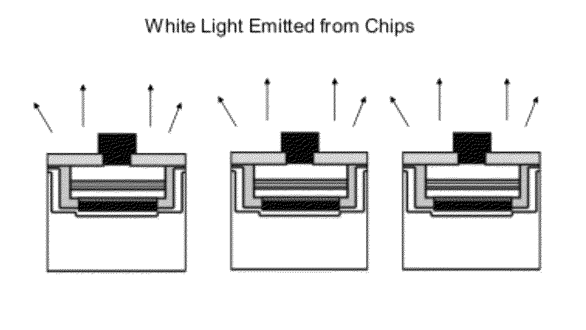
Vertical light emitting diodes (LED) having metal substrate and spin coated phosphor layer for producing white light
a technology of light-emitting diodes and metal substrates, applied in the direction of basic electric elements, electrical equipment, semiconductor devices, etc., can solve the problems of uneven color, complex drive circuits, and inability to generate white light of the desired tone, so as to reduce the amount of phosphor indicated, reduce the cost of producing white led, and reduce the effect of ligh
- Summary
- Abstract
- Description
- Claims
- Application Information
AI Technical Summary
Benefits of technology
Problems solved by technology
Method used
Image

Examples
Embodiment Construction
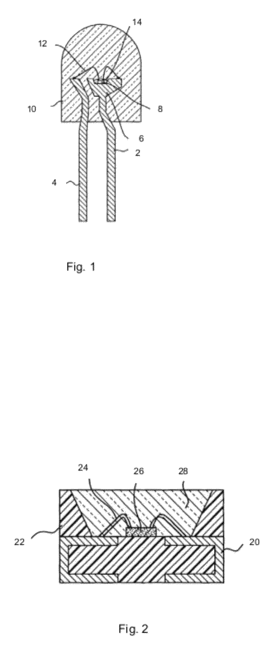
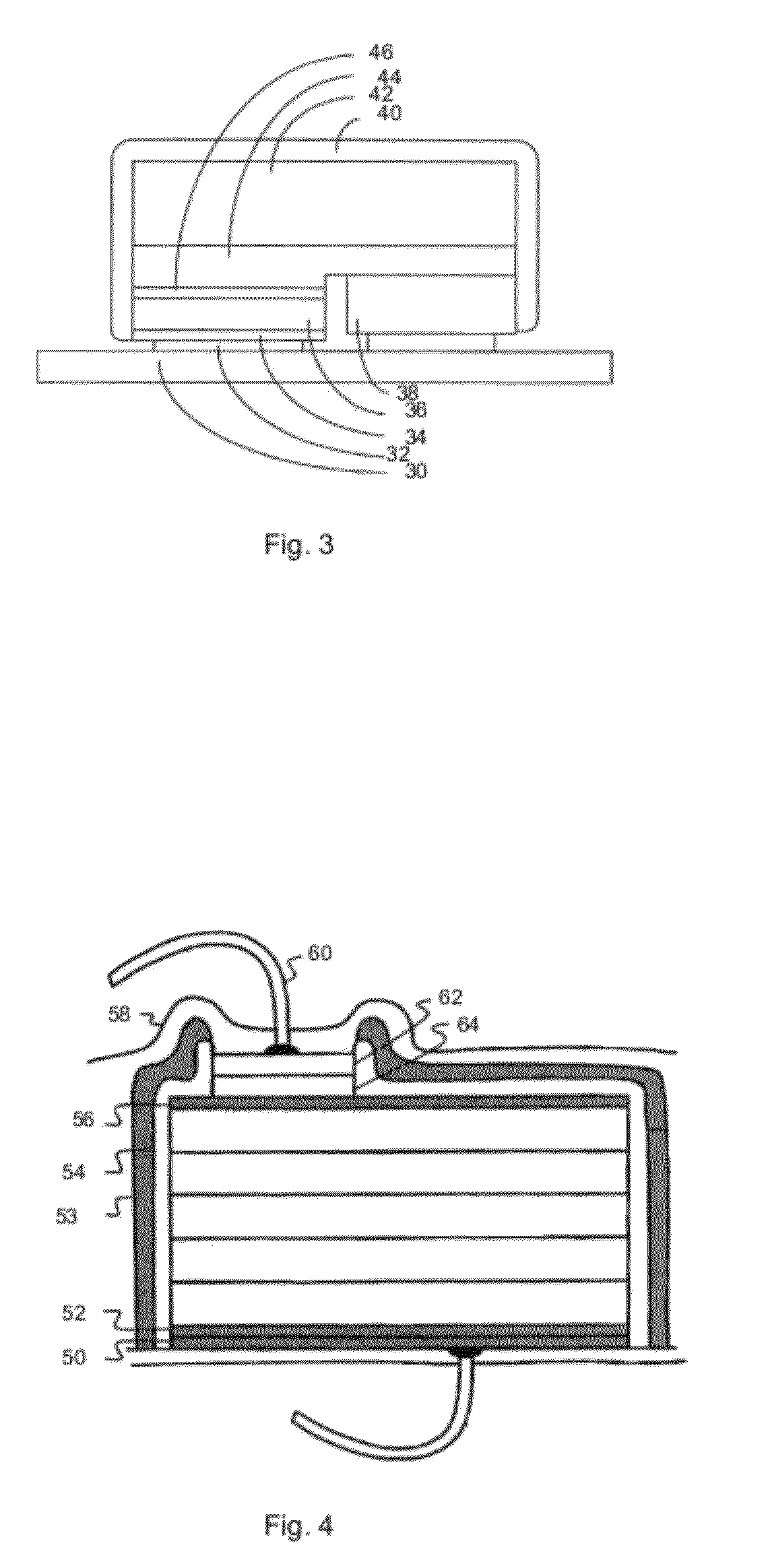
[0025]With reference to the accompanying drawings, embodiments of the present invention will be described. In reading the detailed description, the accompanying drawings may be referenced at the same time and considered as part of the detailed description.
[0026]FIG. 5 shows an exemplary structure of one embodiment of a vertical-LED wafer. Each LED includes a metal substrate 70 made from a laser lift-off process. A p-electrode 72 is positioned above the metal substrate 70. Next, a light reflector and p-contact 74 and a p-GaN portion 76 are positioned above the p-electrode 72. An active region 78 (including a multi-quantum well (MQW)) is formed, and an n-GaN portion 82 is formed above the active region 78. The n-GaN has an exposed surface 80.
[0027]The LED is formed by depositing a multilayer epitaxial structure above a carrier substrate such as sapphire; depositing at least one metal layer above the multilayer epitaxial structure to form a metal substrate 70; and removing the carrier ...
PUM
 Abstract
Description
Claims
Application Information