Method and apparatus for fault identification in a power tansmission line

a technology of transmission line and fault identification, applied in the field of power transmission, can solve the problems of power frequency capacitive coupling voltage very low, system stability may be threatened, and primary devices may be damaged, so as to reliably distinguish a temporary fault

Active Publication Date: 2014-03-25
HITACHI ENERGY LTD
View PDF1 Cites 4 Cited by
  • Summary
  • Abstract
  • Description
  • Claims
  • Application Information

AI Technical Summary

Benefits of technology

[0006]An embodiment of the invention provides a method for fault identification in a transmission line, so as to reliably distinguish a temporary fault (i.e. a transient fault) from a permanent fault in the case that a single-phase fault occurs in the transmission line and to avoid the reclosing of a circuit breaker when the fault is a permanent fault.

Problems solved by technology

However, if a transmission line with a permanent fault is auto-reclosed, there may be two risks, the first risk is that the primary devices may be damaged, and the second risk is that the system stability may be threatened.
As a result, the power frequency capacitive coupling voltage may be very low in the case of either a permanent fault or a temporary fault.
In this case, the methods based on the capacitive coupling voltage fail to distinguish a temporary fault from a permanent fault.

Method used


Image

  • Method and apparatus for fault identification in a power tansmission line
  • Method and apparatus for fault identification in a power tansmission line
  • Method and apparatus for fault identification in a power tansmission line

Examples


Embodiment Construction

[0019]Exemplary embodiments of the present invention are described in conjunction with the accompanying drawings hereinafter. For the sake of clarity and conciseness, not all the features of actual implementations are described in the specification. However, it is to be appreciated that, during developing of any of such actual implementations, numerous implementation-specific decisions must be made to achieve the developer's specific goals, for example, compliance with system-related and business-related constraints which will vary from one implementation to another. Moreover, it is also to be appreciated that, such a development effort might be very complex and time-consuming, but may nevertheless be a routine task for those skilled in the art having the benefit of this disclosure.

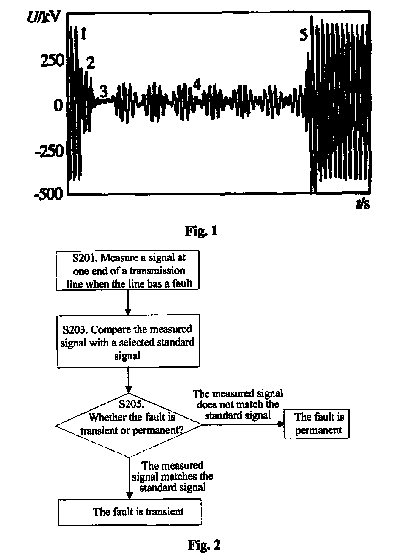
[0020]For a line with shunt reactors, when there is a transient single-phase fault and a fault-phase circuit breaker is opened, the fault point will have a fault arcing, named as secondary arc. The variat...


PUM


Abstract

A method and apparatus for fault identification in a transmission line are provided. The method may include measuring at an end of the transmission line when the transmission line has a fault to obtain a measured signal, comparing the measured signal with a predefined standard signal, the predefined standard signal having beat frequency characteristic; and identifying that the fault is a transient fault if the measured signal matches the predefined standard signal according to a result of the comparison, or the fault is a permanent fault if the measured signal does not match the predefined standard signal according to the result of the comparison.

Description

RELATED APPLICATION[0001]This application is a national filing of PCT application Serial No. PCT / CN2008 / 072191, filed Aug. 29, 2008.FIELD OF INVENTION[0002]The invention relates to the field of power transmission, and more particularly to a method for fault identification in a transmission line when the transmission line has a fault.BACKGROUND OF THE INVENTION[0003]For a transmission line, there generally exist two types of fault, i.e. permanent fault and temporary fault. And for HV / EHV system, over 90% of the faults are single-phase faults, and over 80% of the single-phase faults are temporary faults. Auto-reclosing is an effective way to improve the stability and continuity of a power system. However, if a transmission line with a permanent fault is auto-reclosed, there may be two risks, the first risk is that the primary devices may be damaged, and the second risk is that the system stability may be threatened. So it is very important to distinguish temporary faults from permanen...

Claims


Application Information

Patent Timeline
Patent Type & Authority Patents(United States)
IPC IPC(8): G01R31/02
CPCG01R31/085H02H3/066
Inventor YANG, YINGSU, BINJING, LEILIU, QIANJIN
Owner HITACHI ENERGY LTD
Why Eureka
Try Eureka