Passive multi-band duplexer

a multi-band duplexer and passive technology, applied in the field of radio frequency duplexers, can solve the problems of large size, large cost of saw resonators, and narrow guard band, and achieve the effect of reducing size and cos

Active Publication Date: 2014-03-25
QORVO US INC
View PDF13 Cites 33 Cited by
  • Summary
  • Abstract
  • Description
  • Claims
  • Application Information

AI Technical Summary

Benefits of technology

[0010]The first and second groups of sub-band bandpass filters may include SAW resonators. However, by using the first and second tunable LC bandpass filters to shape the bandpass filter response of the first and second bandpass filters, fewer SAW resonators may be needed, thereby reducing size and cost. In one embodiment of the passive multi-band duplexer, a first antenna switching circuit is coupled between the first group of sub-band bandpass filters and the common port and a second antenna switching circuit is coupled between the second group of sub-band bandpass filters and the common port. In an alternate embodiment of the passive multi-band duplexer, the first bandpass filter is a transmit bandpass filter and the second bandpass filter is a receive bandpass filter, such that the first antenna switching circuit is coupled between the first group of sub-band bandpass filters and the common port, and a tunable phasing network and the second antenna switching circuit are coupled in series between the second group of sub-band bandpass filters and the common port.

Problems solved by technology

However, since the transmit frequency and the receive frequency must typically both fall within a single RF communications band, the guard band may be fairly narrow.
However, SAW resonators tend to be relatively expensive and large.

Method used


Image

  • Passive multi-band duplexer
  • Passive multi-band duplexer
  • Passive multi-band duplexer

Examples


Embodiment Construction

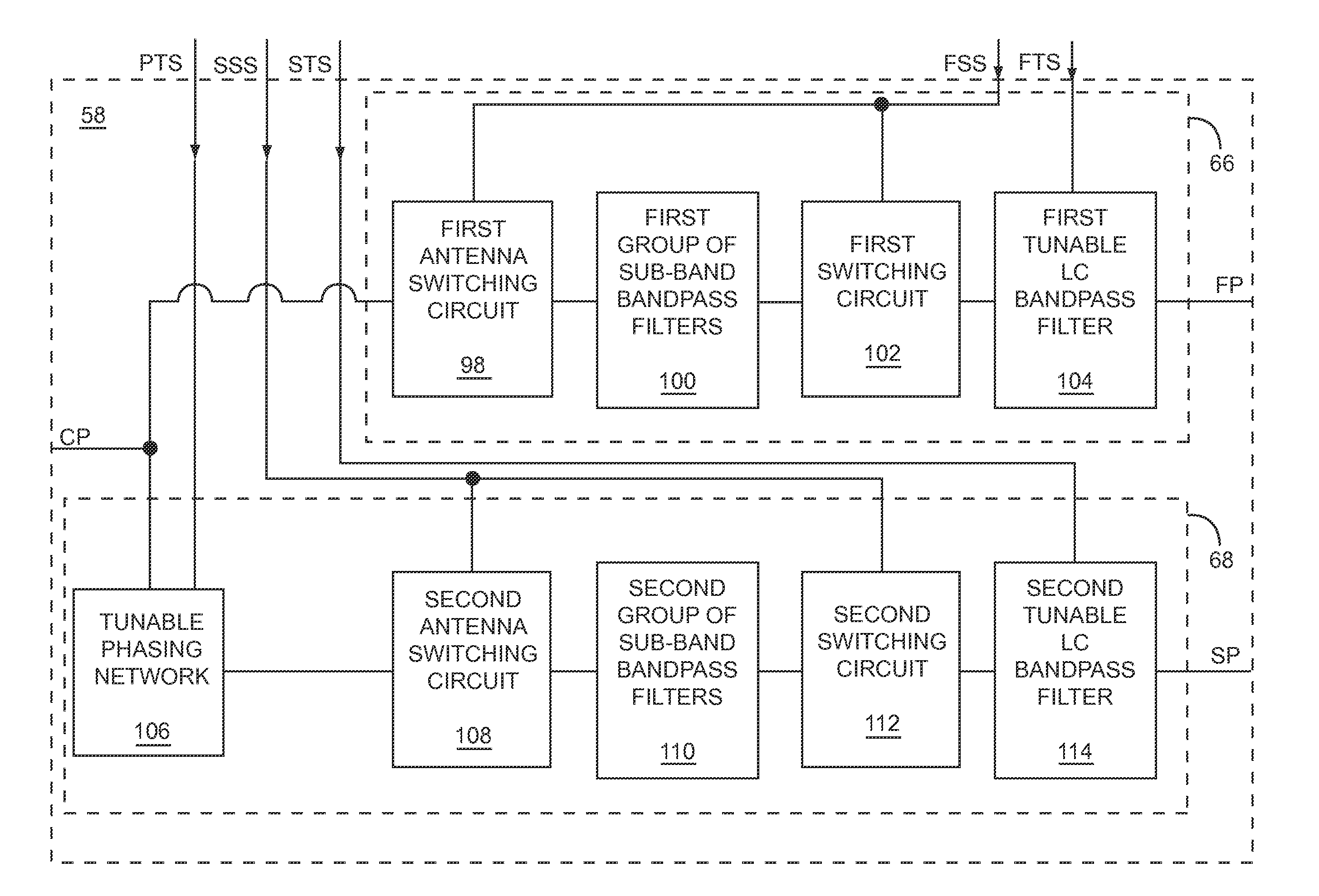
[0009]The present disclosure relates to a passive multi-band duplexer having a first bandpass filter and a second bandpass filter. The first bandpass filter includes a first group of sub-band bandpass filters, a first switching circuit, and a first tunable LC bandpass filter coupled in series between a common port and a first port of the passive multi-band duplexer. Similarly, the second bandpass filter includes a second group of sub-band bandpass filters, a second switching circuit, and a second tunable LC bandpass filter coupled in series between the common port and a second port of the passive multi-band duplexer. A first band of the passive multi-band duplexer, such as a transmit band, is chosen by selecting one of the first group of sub-band bandpass filters using the first switching circuit that matches the first band and tuning the first tunable LC bandpass filter to the first band. Similarly, a second band of the passive multi-band duplexer, such as a receive band, is chosen...


PUM


Abstract

The present disclosure relates to a passive multi-band duplexer having a first bandpass filter and a second bandpass filter. The first bandpass filter includes a first group of sub-band bandpass filters, a first switching circuit, and a first tunable LC bandpass filter. Similarly, the second bandpass filter includes a second group of sub-band bandpass filters, a second switching circuit, and a second tunable LC bandpass filter. A first band of the passive multi-band duplexer, such as a transmit band, is chosen by selecting one of the first group of sub-band bandpass filters and tuning the first tunable LC bandpass filter to the first band. Similarly, a second band of the passive multi-band duplexer, such as a receive band, is chosen by selecting one of the second group of sub-band bandpass filters and tuning the second tunable LC bandpass filter to the second band.

Description

[0001]This application claims the benefit of provisional patent application Ser. No. 61 / 228,447, filed Jul. 24, 2009, and provisional patent application Ser. No. 61 / 297,172, filed Jan. 21, 2010, the disclosures of which are hereby incorporated herein by reference in their entireties.FIELD OF THE DISCLOSURE[0002]Embodiments of the present disclosure relate to radio frequency (RF) duplexers, which may be used in full duplex communications systems.BACKGROUND OF THE DISCLOSURE[0003]RF communications systems typically communicate using at least one of three different modes of operation. The first mode, called simplex, is a one-way mode of operation, in which a transmitter from one location transmits data to a receiver at another location. For example, a broadcast radio station transmits data one-way to radios. The second mode, called half duplex, is a two-way mode of operation, in which a first transceiver communicates with a second transceiver; however, only one transceiver transmits at...

Claims


Application Information

Patent Timeline
Patent Type & Authority Patents(United States)
IPC IPC(8): H01P1/20H03H9/46H03H7/01
CPCH03H2210/036H03H9/706H01P1/213H03H7/465H03H2210/025H03H7/01H03H2210/033H01P1/20H03H2250/00H03H9/725H03H2210/026H03H2210/012H03H9/46
Inventor COSTA, JULIOCARON, JOSHUA J.GILLENWATER, TODD
Owner QORVO US INC
Why Eureka
Try Eureka