

Railroad car wheel truck
Patent Information
- Authority / Receiving Office
- US · United States
- Patent Type
- Patents(United States)
- Current Assignee / Owner
- CRRC YANGTZE CO LTD
- Publication Date
- 2014-04-01
Smart Images
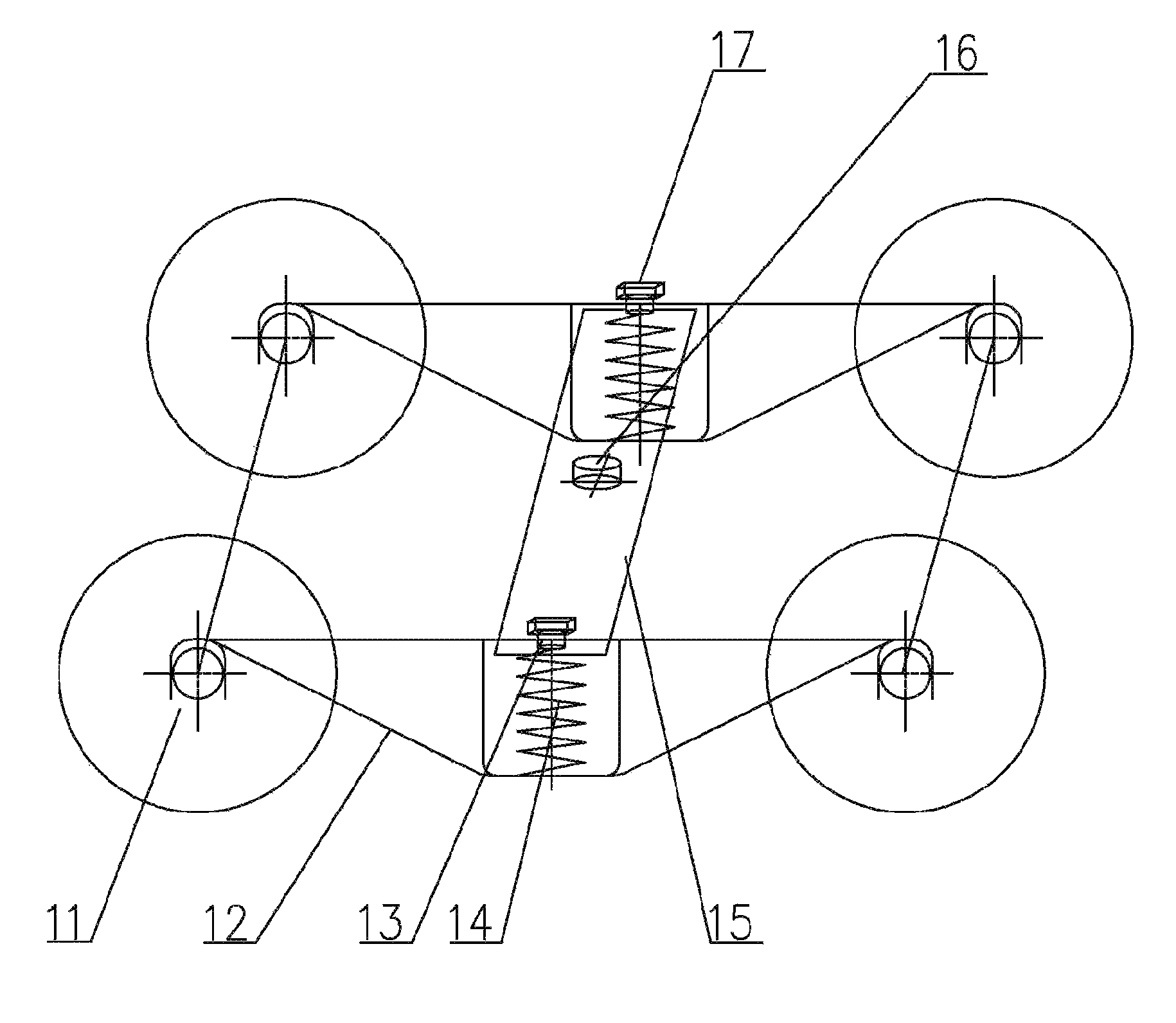
Figure 1 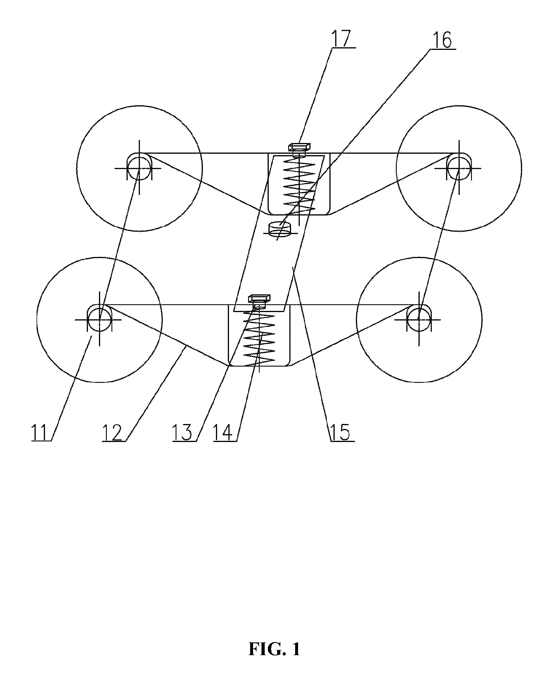
Figure 2 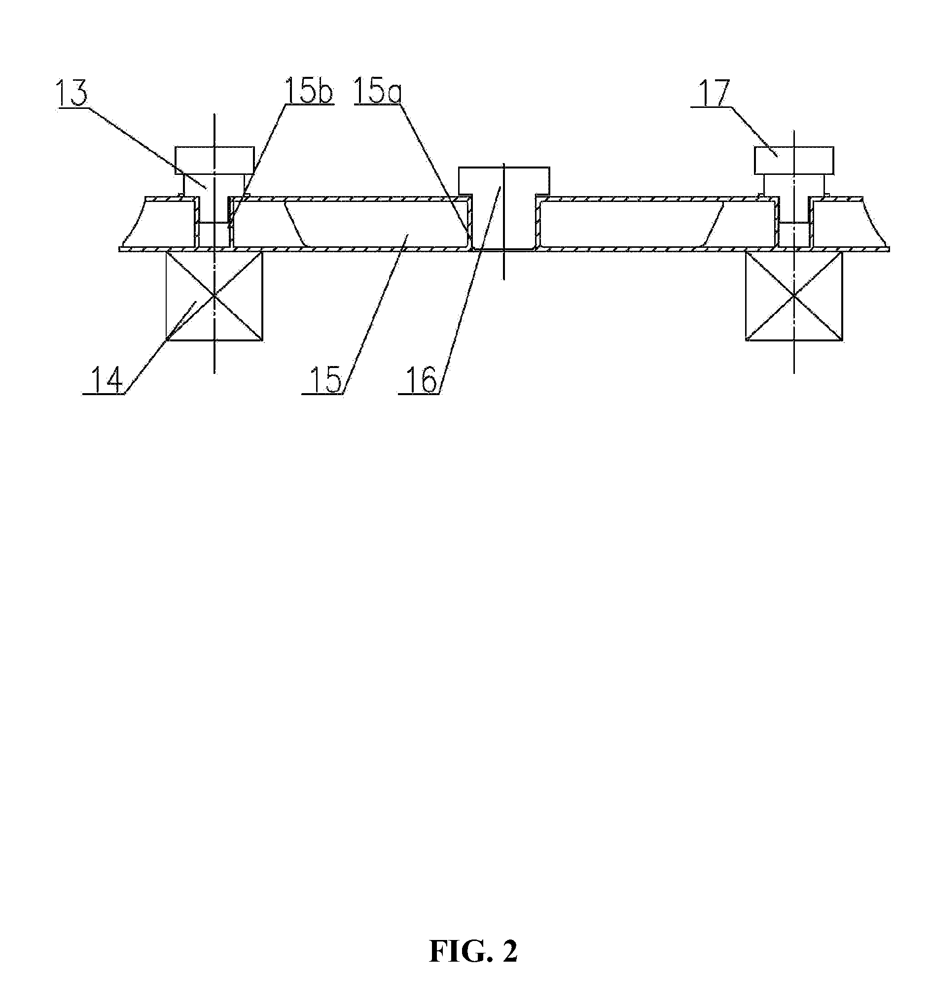
Figure 3
Abstract
Description
CROSS-REFERENCE TO RELATED APPLICATIONS
[0001] This application is a continuation-in-part of International Patent Application No. PCT / CN2010 / 079599 with an international filing date of Dec. 9, 2010, designating the United States, now pending, and further claims priority benefits to Chinese Patent Application No. 201010176894.1 filed May 14, 2010. The contents of all of the aforementioned applications, including any intervening amendments thereto, are incorporated herein by reference. Inquiries from the public to applicants or assignees concerning this document or the related applications should be directed to: Matthias Scholl P.C., Attn.: Dr. Matthias Scholl Esq., 14781 Memorial Drive, Suite 1319, Houston, Tex. 77079.BACKGROUND OF THE INVENTION
[0002] 1. Field of the Invention
[0003] The invention relates to a wheel truck of a railroad freight car.
[0004] 2. Description of the Related Art
[0005] As a critical part of a railroad freight car, a typical wheel truck includes two side frame assemb...