Outdoor solar light with multi-panel solar array

a solar array and solar energy technology, applied in the field of solar energy-powered light systems, can solve the problems of inherently susceptible to poor recharging characteristics, reduced cost of light-emitting diodes, increased output of light-emitting energy, etc., to maximize solar radiation exposure, maximize solar energy generation, and maximize the effect of solar radiation

Inactive Publication Date: 2014-04-01
SKY RICH STAR LTD
View PDF2 Cites 3 Cited by
  • Summary
  • Abstract
  • Description
  • Claims
  • Application Information

AI Technical Summary

Benefits of technology

[0007]The outdoor lighting fixture of the present invention provides a solar powered lighting fixture having a multi-paneled solar array that maximizes the generation of solar energy during the course of a day. More specifically, the outdoor lighting fixture of the present invention includes a multi-paneled solar array housing positioned on an extension rod that includes a plurality of solar panels arranged in a slanted configuration about the periphery of the housing unit. The housing unit is positioned on an extension rod so as to be elevated above the ground but below the actual light fixture. Employing a housing unit separate from the light fixture permits a greater variety of shapes to be used for the light fixture. Moreover, it allows the individual solar panels to be positioned at an optimal angle for maximizing exposure to solar radiation. Each of the solar panels is independent of the others, charging the battery separately so as not interfere with the other solar panels. In a preferred embodiment, multiple pairs of solar panels are arranged on opposing sides of the housing unit.
[0008]By including a multi-paneled solar array on the outdoor lighting fixture of the present invention, the exposure to, and hence the generation of, solar energy is maximized during the course of a day. That is, by positioning a multi-paneled solar array housing on an extension rod in accordance with the present invention, one or more of the individual solar panels is optimally positioned for receiving solar energy. Thus, with this added functionality, the outdoor lighting fixture of the present invention is better able to recharge its batteries during daylight hours.

Problems solved by technology

Similarly, while light emitting diodes had only limited applications for many years, both the cost of light emitting diodes has decreased and the output of light energy has increased.
While such outdoor lighting fixtures are satisfactory in many instances, they are inherently suseptible to poor recharging characteristics because the natural movement of the sun inherently insures that the solar array is positioned optimally to receive the sun light for only a portion of the day.

Method used


Image

  • Outdoor solar light with multi-panel solar array
  • Outdoor solar light with multi-panel solar array
  • Outdoor solar light with multi-panel solar array

Examples


Embodiment Construction

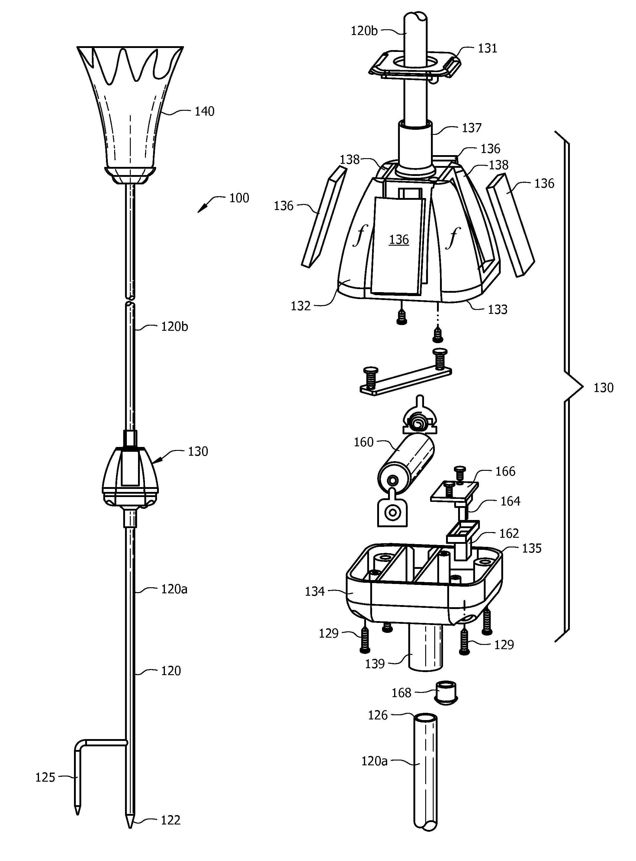
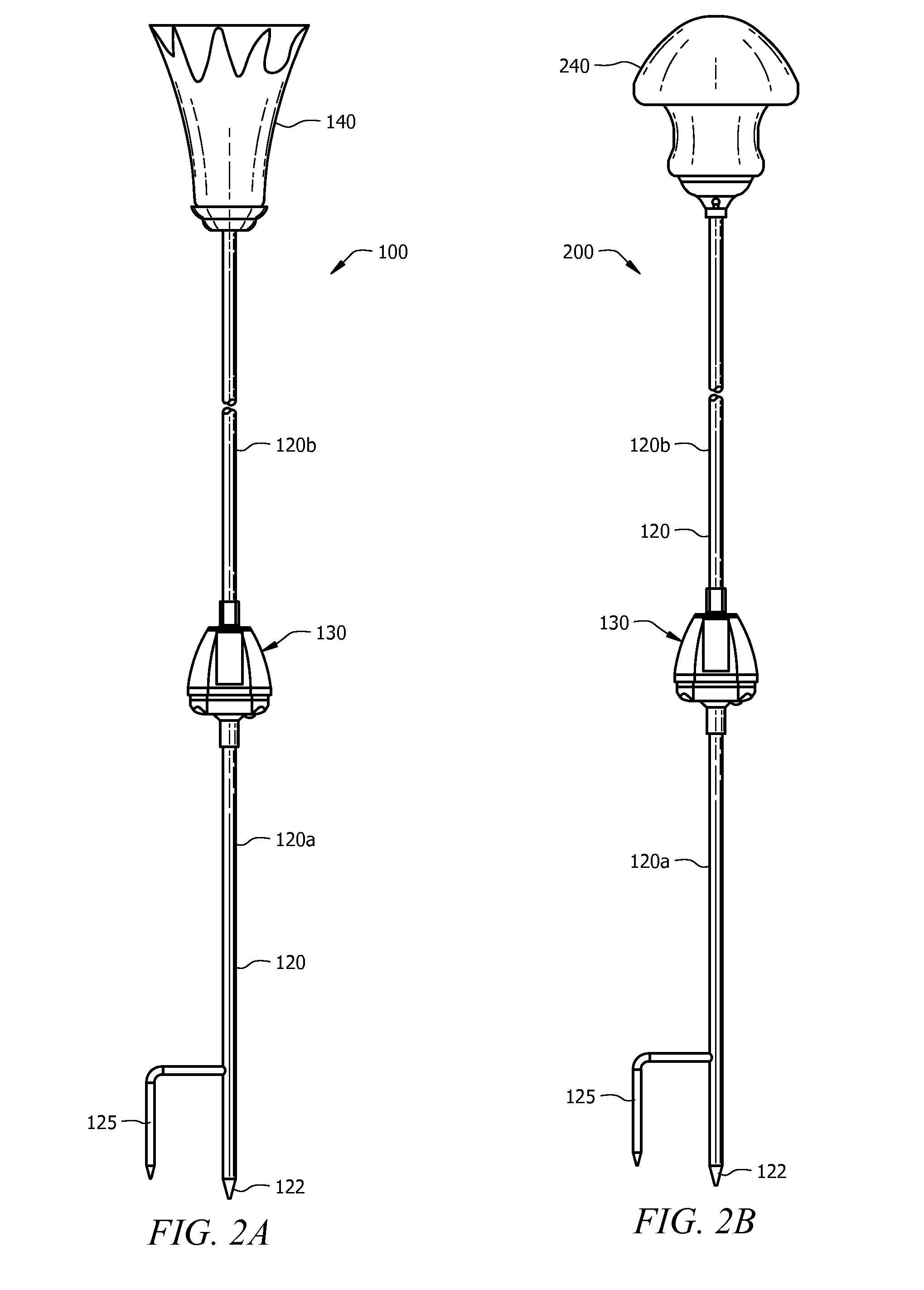
[0019]Preferred embodiments of the outdoor light fixture of the present invention are depicted in FIGS. 2A and 2B. Both embodiments include an extension shaft 120 having a ground spike 122 on one end and a light fixture element on the opposing end with a multi-panel solar array 130 configured therebetween. The extension shaft 120 includes a lower portion or section 120a configured below the multi-panel solar array housing 130 and an upper portion or section 120b configured above the multi-panel solar array housing 130. While the lower portion or section 120a of the extension shaft 120 may be of either solid or hollow construction, upper portion or section 120b must be hollow in order to for a conduit for electrically connecting the multi-panel solar array 130 to the light fixture element. The lower portion of the extension shaft 120 may further include a stabilization spike 125 configured parallel to and offset from the extension shaft 120.

[0020]The extension shaft 120 may comprise ...


PUM


Abstract

A solar powered lighting fixture having a multi-paneled solar array that maximizes the generation of solar energy during the course of a day. The outdoor lighting fixture of the present invention includes a multi-paneled solar array housing positioned on an extension rod that includes a plurality of solar panels arranged in a slanted configuration about the periphery of the housing unit. The housing unit is positioned on the extension rod so as to be elevated above the ground but below the actual light fixture. Employing a housing unit separate from the light fixture permits a greater variety of shapes to be used for the light fixture. Moreover, it allows the individual solar panels to be positioned at an optimal angle for maximizing exposure to solar radiation. Each of the solar panels is independent of the others, charging the battery separately so as not interfere with the other solar panels.

Description

BACKGROUND OF THE INVENTION[0001]1. Technical Field of the Invention[0002]The present invention pertains to solar powered light systems such as those used primarily in close proximity to residences for the purpose of illuminating walkways or providing decorative lighting; more particularly the present invention pertains to a system for enhancing the collection of solar energy to power solar powered outdoor lights.[0003]2. Description of the Related Art[0004]In the past several years, the technology associated with solar panels and light emitting diodes has seen rapid development. Specifically, while solar panels were once almost a novelty item or an item used only in remote locations, both the cost of solar panels has decreased and the output of electrical energy from solar panels has increased. Similarly, while light emitting diodes had only limited applications for many years, both the cost of light emitting diodes has decreased and the output of light energy has increased. Accord...

Claims


Application Information

Patent Timeline
Patent Type & Authority Patents(United States)
IPC IPC(8): F21L13/00
CPCF21S8/08F21V23/0464F21W2131/10F21V21/0824F21S9/035F21Y2101/02F21Y2115/10Y02B20/72
Inventor CHEN, CHI, GON
Owner SKY RICH STAR LTD
Why Eureka
Try Eureka