
Area denial device

a denial device and area technology, applied in the field of defense means, can solve the problems of limiting the life of insurgents and civilians, the possibility of civilian injury and death is very high, and the possibility of accidental injury or death of friendly forces is also high, so as to reduce the burden, reduce the ability of insurgents to walk or function, and reduce the risk of casualties

Inactive Publication Date: 2014-04-08
AREA DENIAL SYST
View PDF8 Cites 3 Cited by
  • Summary
  • Abstract
  • Description
  • Claims
  • Application Information

AI Technical Summary

Benefits of technology

The lance mine effectively incapacitates enemy personnel without causing life-threatening injuries, allows for identification and tracking, and can be safely deployed and neutralized, reducing the risk of civilian casualties and accidental injuries.

Problems solved by technology

Explosive anti-personnel landmines cause thousands of deaths and severe, life limiting injuries amongst insurgents and civilians every year.
With an explosive anti-personnel landmine, the possibility of civilian injury and death is very high.
The possibility of accidental injury or death to friendly forces is also high, both in the deployment and recovery of the landmine.

Method used


Image

  • Area denial device
  • Area denial device
  • Area denial device

Examples


Embodiment Construction

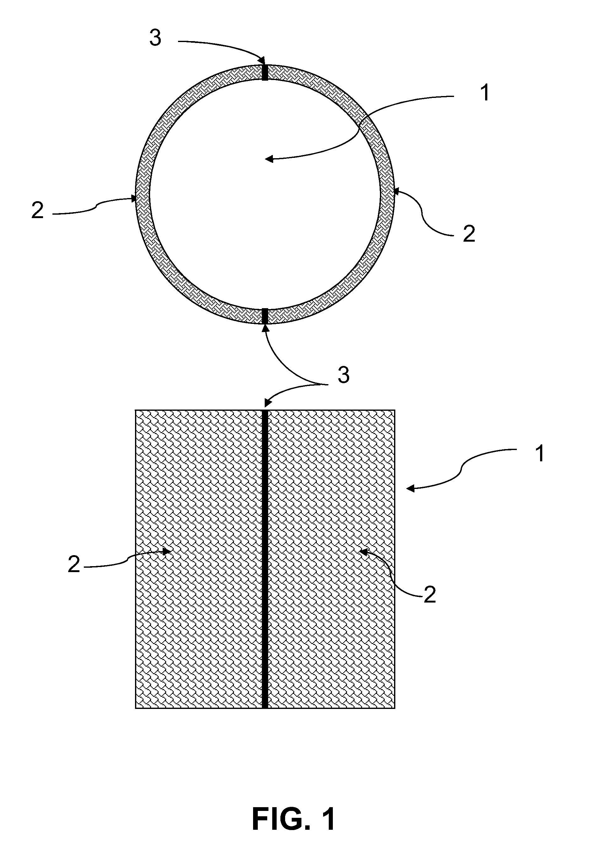
[0107]FIG. 1 is a cross-sectional view of a segmented cylinder 1, open at both ends. The two halves 2, are segmented at junction points 3.

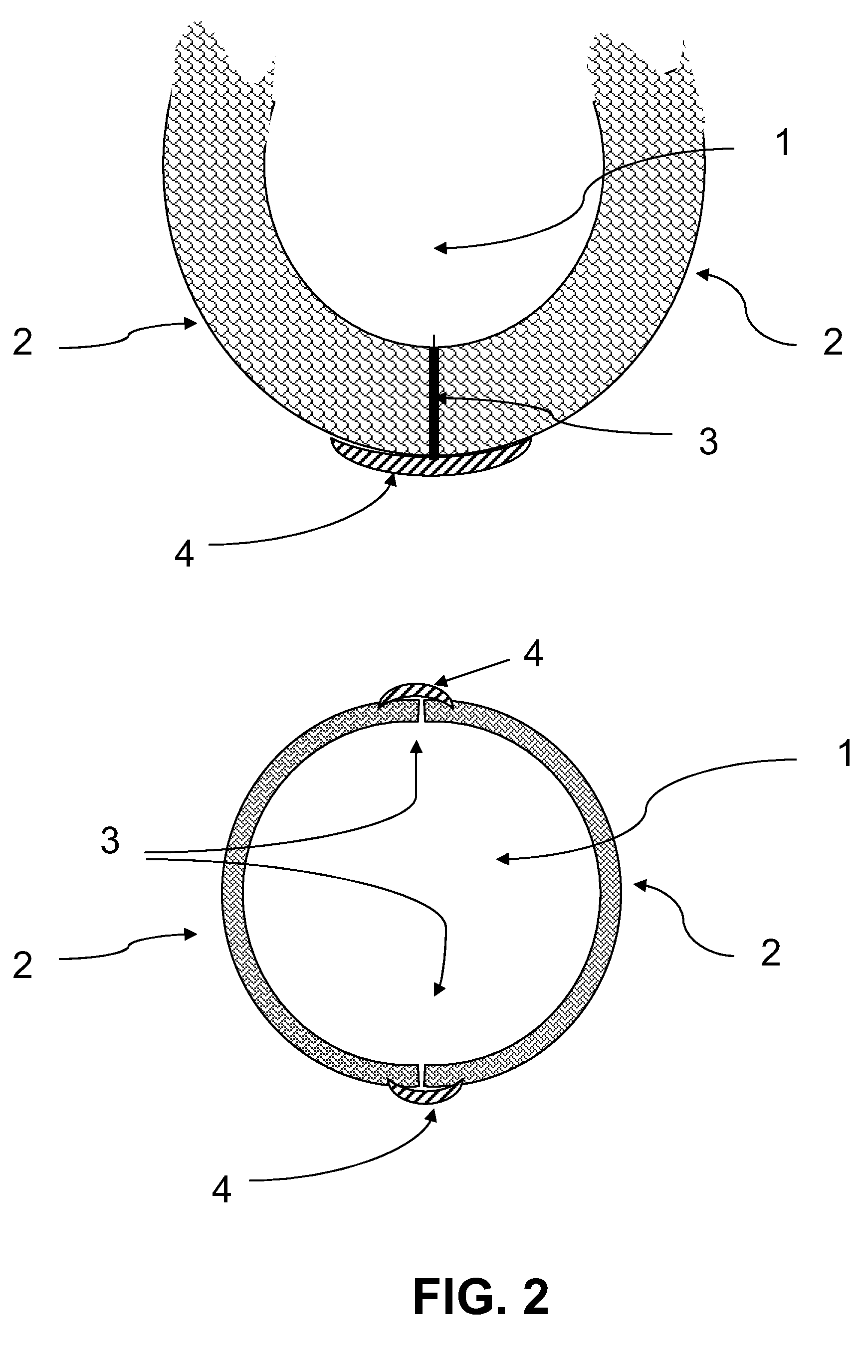
[0108]FIG. 2 is a top down view of cylinder 1. Cylinder 1 is shown with two partial halves to better show junction point 3 and structural reactive material 4. The two halves 2 are shown joined at junction points 3 by structural reactive material 4. Structural reactive material 4 can be a reactive metal, plastic, polymer, thermally reactive material, or any reactive material that will secure cylinder 1 halves 2 securely and then release the halves 2 by becoming nonstructural at a predetermined interval after exposure to the environment.

[0109]FIG. 3 demonstrates the separation of cylinder 1 into its two component halves 2, separating at the junction points 3 when the structural reactive material 4 has reacted and become nonstructural.

[0110]FIG. 4 shows a stereotypical firing pin and detonator arrangement in cross section. Cylinder halves 2 are still...


PUM


Abstract

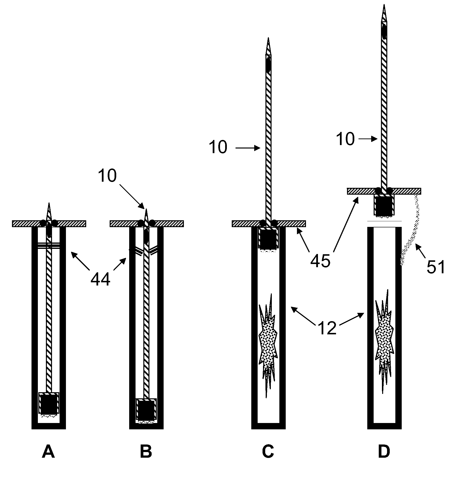
A propelled lance provides a wounding non-lethal anti-insurgent action when stepped on by piercing an enemy insurgent's foot with a lance penetrator. The lance penetrator lodges in the foot and further penetration is impeded by a stop plate. The lance penetrator may insert an RFID or other identifiable device or other payload into the insurgent. The lance penetrator provides anti-personnel, anti-vehicle and anti-robot action.

Description

FIELD OF THE INVENTION[0001]The present invention relates to defense means, particularly to the field of non-lethal area denial devices, and to non-lethal devices for disabling, RFID tagging and marking enemy personnel, vehicles and robots. The present invention relates to devices such as land mines and other area denial devices that, after deployment, are armed or arm themselves through the action of an integrated component, and later are disarmed or disarm themselves through a similar process.SUMMARY OF THE INVENTION[0002]The following description of preferred embodiments will provide a summary description of the present invention.[0003]Explosive anti-personnel landmines cause thousands of deaths and severe, life limiting injuries amongst insurgents and civilians every year. It is estimated that over 20,000 civilians, including many children, are permanently maimed or killed a year by anti-personnel landmines. As a result of wide-spread international concern about the high number ...

Claims


Application Information

Patent Timeline
Patent Type & Authority Patents(United States)
IPC IPC(8): F42B22/02
CPCF42B23/04F42B12/40G09F3/00F41H13/0093F42B23/16F42B12/36F41H11/08
Inventor BURDINE, ROBERT VANBURDINE, DOROTHY DEVINE
Owner AREA DENIAL SYST
Learn More