Window well projection system

Inactive Publication Date: 2014-04-08
CLOCK WESLEY
View PDF12 Cites 12 Cited by
  • Summary
  • Abstract
  • Description
  • Claims
  • Application Information

AI Technical Summary

Benefits of technology

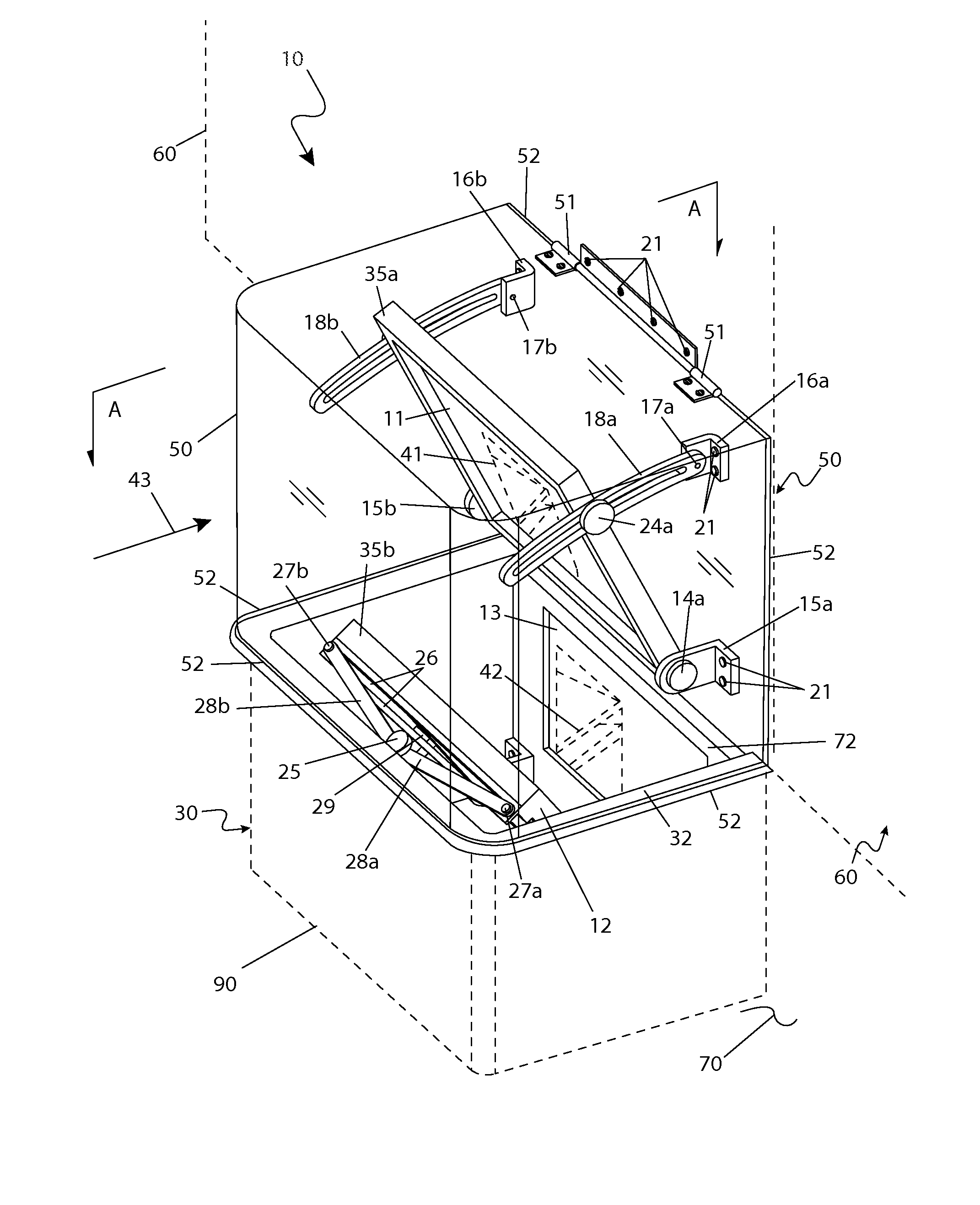
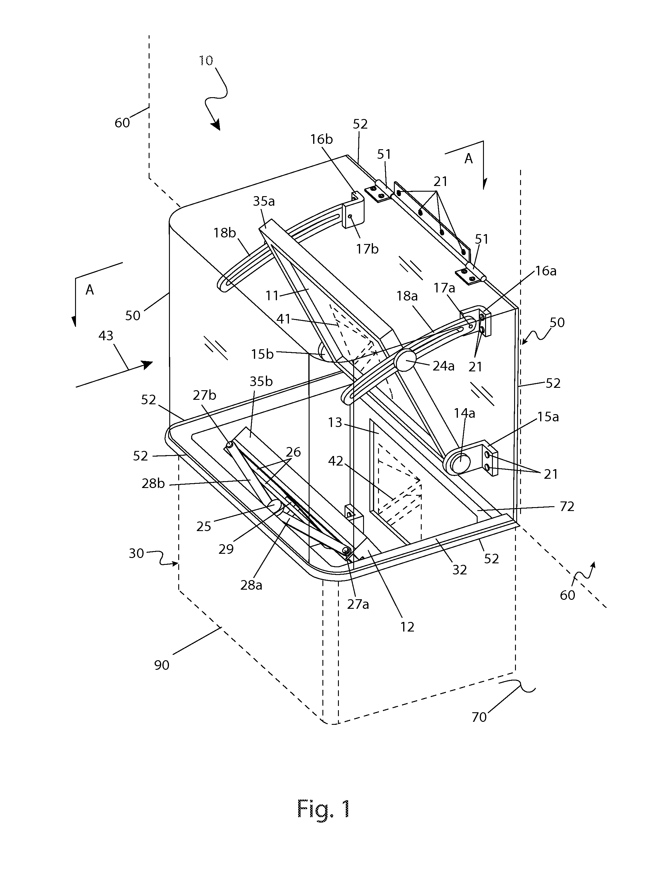
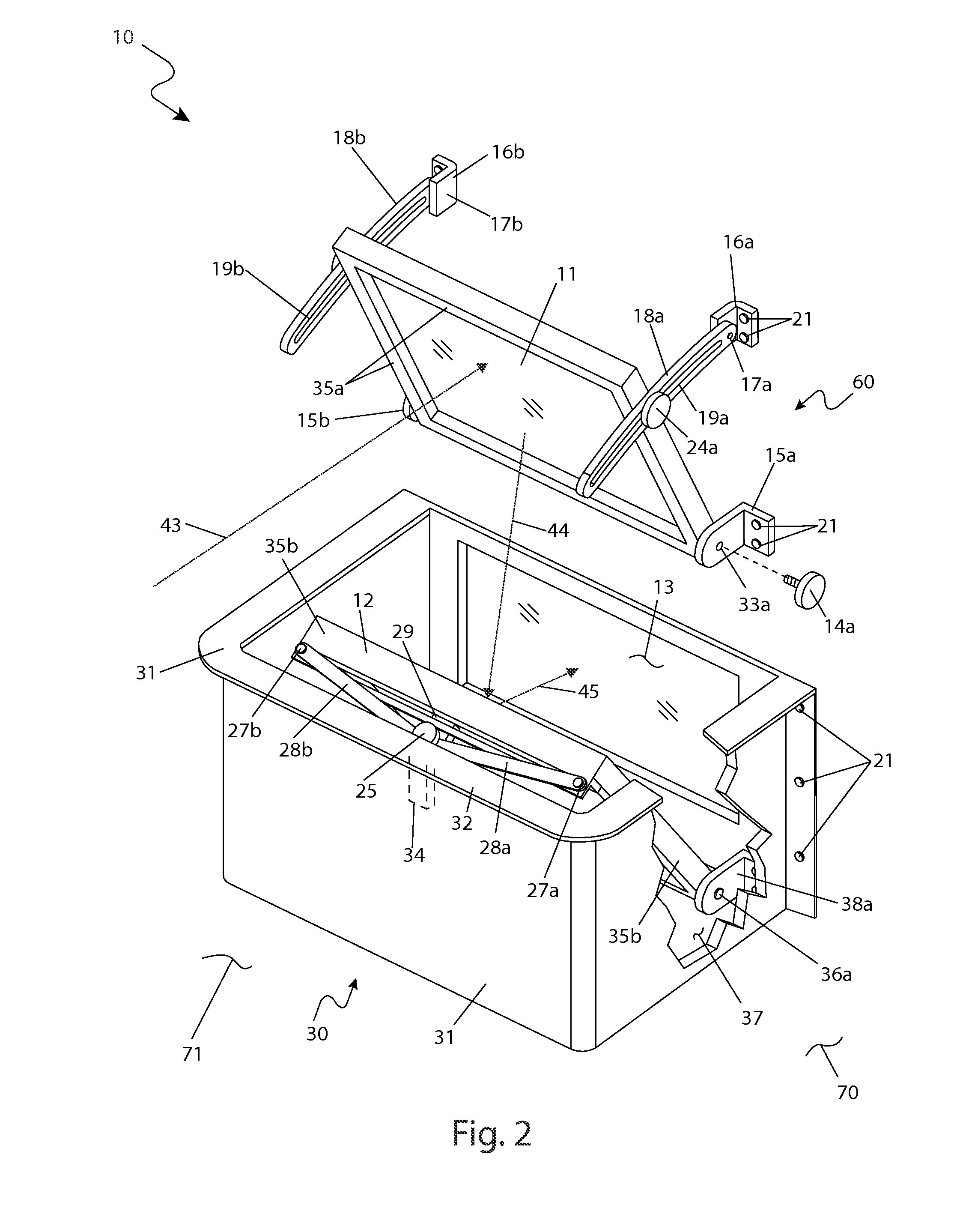
[0011]Yet still another object of the present invention is to prevent accumulation of debris with the window well which can negatively impact the path of the ambient light. The cover is constructed of a weather-resistant material and is sealed about the building structure and well with a common flange or gasket. The cover further includes a hinge portion which enables access to the first mirror, second mirror, and interior of the window well for purposes of cleaning, maintenance, adjustment, or repair.
[0012]Yet still another object of the present invention is to provide a range of positional and angular adjustment for both the first mirror and second mirror to allow a user to selectively configure the system as needed for a specific window well. The first minor is attached at a lower end to a pair of pivot pin brackets which allow rotational motion of the first minor and at a top end to a pair of adjustment brackets including a curved track for fastening the first minor at a desired angle. The second mirror is similarly attached at a lower end to a pair of pivot pin brackets and further comprises a pair of links and a locking knob at a top end which enable selective, securable adjustment of the angle of the second mirror.
[0013]Yet still another object of the present invention is to enable use with a variety of types of minors and viewing panes to provide a range of customizability in the function and effectiveness of the passage of ambient light based upon environment, desired use, and the like. The mirrors can include common features such as a various flat or curved profiles and magnification of the transmitted view while the viewing pane can provide common light-filtering constructions such as a transparent construction, a tinted construction, or a polarized construction.
[0014]Yet still another object of the present invention is to comprise at least one (1) alternate embodiment including a pair of motors attached to

Problems solved by technology

Sub-grade rooms such as basements are often provided with windows, but due to their below grade construction, such windows are typically located within a window well which provides room occupants only a small amount of light and a view of the inside of the window well.
However, this limits many of the above-stated positive benefits of windows such as the pleasant atmosphere provided by a view of the outdoors.
Lack of a strong incoming light generally increases electric ligh

Method used


Image

  • Window well projection system
  • Window well projection system
  • Window well projection system

Examples


Embodiment Construction

[0100]The best mode for carrying out the invention is presented in terms of its preferred embodiment, herein depicted within FIGS. 1 through 5, and in terms of an alternate motorized embodiment, herein depicted within FIGS. 6 through 8. However, the invention is not limited to the described embodiment and a person skilled in the art will appreciate that many other embodiments of the invention are possible without deviating from the basic concept of the invention, and that any such work around will also fall under scope of this invention. It is envisioned that other styles and configurations of the present invention can be easily incorporated into the teachings of the present invention, and only one particular configuration shall be shown and described for purposes of clarity and disclosure and not by way of limitation of scope.

[0101]The terms “a” and “an” herein do not denote a limitation of quantity, but rather denote the presence of at least one of the referenced items.

[0102]The p...


PUM


Abstract

A system for basement window wells that enables internal occupants a view of the surrounding outdoor landscape is herein described, comprising a periscope-type mechanism comprising a pair of mirrors which mount within a window well area. An upper portion of the system comprises a mirror which reflects light and scenery downward. A bottom portion of the system comprises a second minor which projects said light and scenery through a below-grade window portion of a building. A protective transparent plastic cover maintains a watertight construction.

Description

RELATED APPLICATIONS[0001]The present invention was first described in and claims the benefit of U.S. Provisional Application No. 61 / 296,913 filed Jan. 21, 2010, the entire disclosures of which are incorporated herein by reference.FIELD OF THE INVENTION[0002]The present invention relates generally to windows mounted within sub-grade window wells, and in particular, to an adjustable mirror assembly for increasing incidence of light from an outdoor area through the window well and window.BACKGROUND OF THE INVENTION[0003]Windows are important building fixtures for primarily two reasons—the ingress of ambient light source into a building, which mitigates energy needs from manmade lighting, and for affording an external view which allows observance of a proximal outdoor area. This view allows persons to both monitor a nearby area and provides a generally more pleasant ambiance which can contribute to general mental wellbeing. The incidence of natural light also provides a number of other...

Claims


Application Information

Patent Timeline
IPC IPC(8): G03B21/28G02B23/08
CPCG02B7/182G03B21/28G02B23/08G02B7/1824
Inventor CLOCK, WESLEY
Owner CLOCK WESLEY
Why Eureka
Try Eureka