Method of controlling the lighting of a room in accordance with an image projected onto a projection surface

a technology of projection surface and lighting, which is applied in the direction of optical radiation measurement, color signal processing circuit, instruments, etc., can solve the problem that standard image projection setups are limited to projecting images, and achieve the effect of enhancing viewer experience and better measuring characteristic features

Inactive Publication Date: 2014-04-08
KONINK PHILIPS ELECTRONICS NV +1
View PDF11 Cites 36 Cited by
  • Summary
  • Abstract
  • Description
  • Claims
  • Application Information

AI Technical Summary

Benefits of technology

[0006]An obvious advantage of the method described above is that any existing projection equipment can be used, since the adjusting of the room lighting is done on the basis of measuring the output of the projector, i.e. the projected image itself, without having to evaluate the underlying video signal or modify the optical output characteristics of the projector to generate the ambient lighting.
[0016]Measurement of the characteristic features of the image projected onto the projection surface can be done electro-optically, which covers all methods of capturing optical characteristics and transforming them into electrical signals. This keeps the input interface at the control unit simple, and allows for easy further processing of the measured data. Therefore, the term “optical sensor” comprises all kinds of sensor capable of capturing the necessary optical characteristics, in particular electro-optical sensors, like photodiodes etc. The light sensor could be connected to the control unit by wire or in a wireless manner. In a wireless embodiment, the sensor could be made self-powered by means of a solar cell that collects the energy from the projector or from the ambient room light.
[0023]As mentioned already, the human eye cannot perceive details outside the centre of the viewing area. Hence zones simply illuminated with one colour matching the part of the projected image at the adjacent edge of the projection screen generate a sense of extension of the image beyond the actual projection area, significantly enhancing the viewer experience.
[0024]In a simple embodiment, each measuring area is represented by just one measuring point. To achieve a better measurement of characteristic features, more measuring points or even an approximately continuous measuring area like a CCD sensor can be used.
[0026]Additional optical sensors may be used for measuring the room lighting. In an improved embodiment, the optical sensors used for measuring the projected image are also used for measuring the room lighting. For this purpose, the control unit has to switch off the room lighting, for example periodically, to enable measuring of the projected image without spurious light from the environment disturbing the measurement.

Problems solved by technology

Standard image projection setups are limited to projecting an image to a projection surface whilst leaving the surrounding area dark.
However, these devices require either specifically designed projection units or at least a control signal derived from the video signal itself.

Method used


Image

  • Method of controlling the lighting of a room in accordance with an image projected onto a projection surface
  • Method of controlling the lighting of a room in accordance with an image projected onto a projection surface
  • Method of controlling the lighting of a room in accordance with an image projected onto a projection surface

Examples


Embodiment Construction

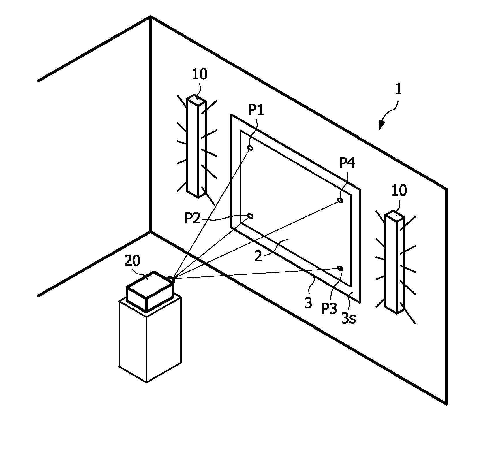
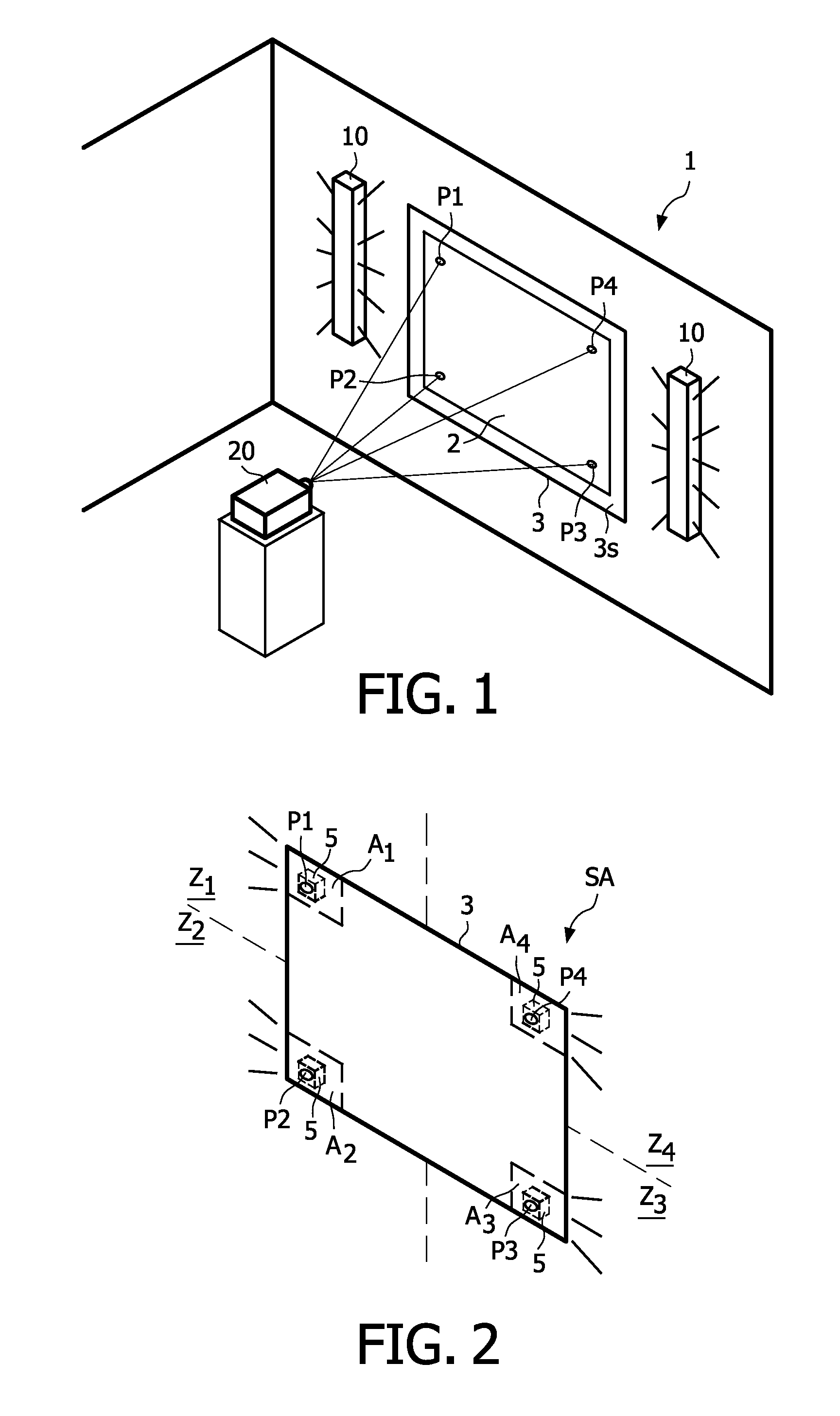
[0041]FIG. 1 shows a system 1 for controlling the lighting of a room in accordance with an image 2 projected onto a projection surface 3s of a projection screen device 3. As a projection unit 20, any apparatus can be used that is designed to project images onto a screen. The projection screen 3 contains four measuring points P1, P2, P3, P4 at the edges of the screen at which optical sensors measure characteristic features of the image 2 projected onto the projection screen 3. In FIG. 2, the projection screen device 3 of the system 1 is shown in more detail. Behind each of the four measuring points P1, P2, P3, P4 a sensor 5 is mounted on a wall in the direction of projection. The screen of the projection screen device 3 is semitransparent at the measuring points P1, P2, P3, P4, and light from the projected image 2 passes through the projection screen to the optical sensors 5 which measure characteristic features of the light passing through.

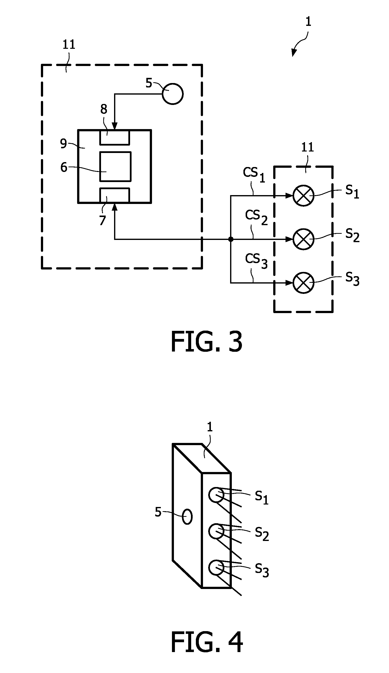
[0042]A control unit, not shown in FIGS. 1 ...


PUM


Abstract

The invention describes a method of controlling a lighting of a room (1) in accordance with a still or moving image (2) projected onto a projection surface (3s), which method comprises optically measuring a number of characteristic features (f) of the projected image and adjusting the room lighting of the room on the basis of the measured characteristic features (f). Furthermore, the invention relates to a system for controlling the lighting of a room (1) in accordance with an image (2) projected onto a projection surface (3s), to a control device (9) for use in such a system, and to a projection screen device (3) for use in such a system. Moreover, the invention relates to a room lighting system (1) for lighting of a room in accordance with an image (2) projected onto a projection surface (3s).

Description

FIELD OF THE INVENTION[0001]The invention relates to a method of controlling the lighting of a room in accordance with an image projected onto a projection surface. The invention further relates to a control system for controlling the lighting of a room in accordance with an image projected onto a projection surface and to a control device and to a projection screen device for use in such a system. Moreover, the invention relates to a room lighting system for lighting of a room in accordance with an image projected onto a projection surface.BACKGROUND OF THE INVENTION[0002]Standard image projection setups are limited to projecting an image to a projection surface whilst leaving the surrounding area dark. PCT / WO 2004 / 112386 A1 describes a device for illuminating the area surrounding a projection screen on the basis of the image data. This illumination allows for more pleasant viewing and generates the sensation of the image being extended beyond the actual projection area. Also, US 2...

Claims


Application Information

Patent Timeline
Patent Type & Authority Patents(United States)
IPC IPC(8): G03B21/00
CPCH04N5/58H05B37/029H04N9/3194H04N9/73H04N9/3197H04N21/42202H04N21/4131H05B47/155
Inventor WENDT, MATTHIAS
Owner KONINK PHILIPS ELECTRONICS NV
Why Eureka
Try Eureka