Facilitated editing of generative design geometry in computer aided design user interface

a technology user interface, applied in the field of computer aided design of physical structures, can solve the problem that the generative design solver does not operate directly, and achieve the effect of facilitating editing of those surfaces, reducing time, and facilitating further processing

Active Publication Date: 2019-11-05
AUTODESK INC
View PDF7 Cites 19 Cited by
  • Summary
  • Abstract
  • Description
  • Claims
  • Application Information

AI Technical Summary

Benefits of technology

[0013]Particular embodiments of the subject matter described in this specification can be implemented to realize one or more of the following advantages. Building a parametric feature recipe for use in converting and combining one or more editable smooth surfaces (e.g., T-Spline surfaces) produced by a generative design process facilitates editing of those surfaces before conversion to B-Rep format and combination into a watertight 3D model in a CAD system. Readily editable smooth surfaces (e.g., T-Spline surfaces) can be modified by the user, rather than requiring mesh editing, which can be time consuming, especially for the complex shapes typically created by generative design methods, and an automated workflow for producing B-Rep solids from the edited smooth surfaces can significantly reduce the time needed for the user to create a watertight 3D model that is ready for use in manufacturing. Further, the produced B-Rep solids facilitate further processing in that the precise mathematical surfaces are easier to work with using precise modeling tools and CAD modeling operations (e.g., geometric modeling operations, such as holes, fillets or shells, and creating assembly relationships, such as mechanical joints),
[0014]A generative design editor user interface can be made easier to use and provide significant flexibility for engineers and designers when making revisions to generated geometry (1) for aesthetic reasons, (2) because some aspects of the generated geometry may be too small to be manufactured reliably, and / or (3) to increase the margin of safety and reliability for the object to be manufactured. Using a parametric feature recipe, as described herein, can simplify the user interface for editing generated geometry in a display device while also providing flexibility in modifying the edited geometry multiple times without risking disconnection of the generated geometry from other bodies in the 3D model, thus ensuring that precise, watertight 3D models are produced for use in subsequent CAD / CAM operations.

Problems solved by technology

This automated generation of 3D geometry is often limited to a design space specified by a user of the CAD software, and the 3D geometry generation is typically governed by design objectives and constraints, which can be defined by the user of the CAD software or by another party and imported into the CAD software.
Further, the inputs to a generative design process can include a set of input solids (B-Rep input) that specify boundary conditions for the generative design process, but many modern generative design solvers do not operate directly on the exact surface boundary representation of their input solids.

Method used


Image

  • Facilitated editing of generative design geometry in computer aided design user interface
  • Facilitated editing of generative design geometry in computer aided design user interface
  • Facilitated editing of generative design geometry in computer aided design user interface

Examples


Embodiment Construction

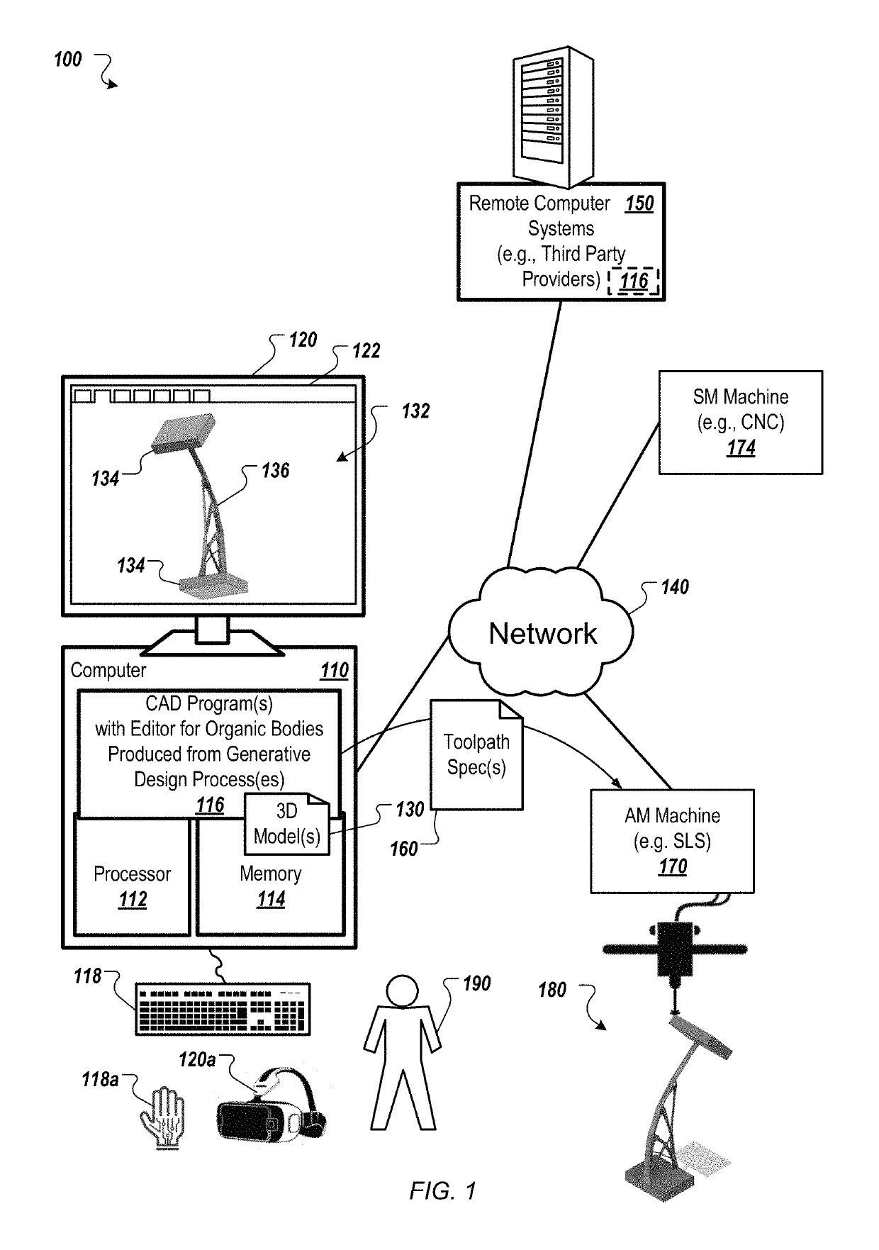
[0029]FIG. 1 shows an example of a system 100 usable to modify generative design geometry in computer aided design of physical structures, which can then be manufactured using additive manufacturing, subtractive manufacturing and / or other manufacturing systems and techniques. A computer 110 includes a processor 112 and a memory 114, and the computer 110 can be connected to a network 140, which can be a private network, a public network, a virtual private network, etc. The processor 112 can be one or more hardware processors, which can each include multiple processor cores. The memory 114 can include both volatile and non-volatile memory, such as Random Access Memory (RAM) and Flash RAM. The computer 110 can include various types of computer storage media and devices, which can include the memory 114, to store instructions of programs that run on the processor 112, including Computer Aided Design (CAD) program(s) 116, which implement three-dimensional (3D) modeling functions and incl...


PUM

PropertyMeasurementUnit
physical structureaaaaaaaaaa
physical structuresaaaaaaaaaa
weightaaaaaaaaaa

Abstract

Methods, systems, and apparatus, including medium-encoded computer program products, for facilitating editing of generative design geometry of physical structures, include a method including: receiving editable smooth surface(s), e.g., a T-Spline, constructed from a mesh obtained using a generative design process; instantiating a parametric feature recipe to connect the editable smooth surface(s) with input solid(s), wherein the parametric feature recipe includes an operation sequence that (i) converts the editable smooth surface(s) into boundary representation format and (ii) combines the boundary representation formatted smooth surface(s) with the input solid(s) to produce a watertight three dimensional model of an object; modifying the editable smooth surface(s) in response to input, while preventing disconnection of the editable smooth surface(s) from the input solid(s); updating a visualization thereof in a user interface; and performing the operation sequence of the parametric feature recipe to produce the watertight three dimensional model of the object.

Description

BACKGROUND[0001]This specification relates to computer aided design of physical structures, which can be manufactured using additive manufacturing, subtractive manufacturing and / or other manufacturing systems and techniques.[0002]Computer Aided Design (CAD) software has been developed and used to generate three-dimensional (3D) representations of objects, and Computer Aided Manufacturing (CAM) software has been developed and used to manufacture the physical structures of those objects, e.g., using Computer Numerical Control (CNC) manufacturing techniques. Typically, CAD software stores the 3D representations of the geometry of the objects being modeled using a boundary representation (B-Rep) format. A B-Rep model is a set of connected surface elements specifying boundaries between a solid portion and a non-solid portion of the modelled 3D object. In a B-Rep model (often referred to as a B-Rep), geometry is stored in the computer using smooth and precise mathematical surfaces, in con...

Claims


Application Information

Patent Timeline
Patent Type & Authority Patents(United States)
IPC IPC(8): G06T17/30G06T17/20G06F17/50G06T19/20B33Y10/00
CPCG06F17/5018G06T17/30G06T17/20B33Y10/00G06T19/20G06T2219/2021G06T2200/24G06T17/10G06F30/23B33Y50/00G06F30/10G06F2113/10G06F2111/02G06F2119/18Y02P10/25Y02P90/02B22F10/18B22F10/28
Inventor STRATER, JEFFREY T.FURUTA, SUGURUSCHNEIDER, KEVIN JOHNFRANK, BRIAN M.SMELL, MICHAEL ANDREWFLOWER, JEAN ALISONSANTHANAM, NANDAKUMAR
Owner AUTODESK INC
Why Eureka
Try Eureka