Printing with merged drops using electrostatic deflection

a technology of electrostatic deflection and printing drops, which is applied in printing, other printing apparatus, etc., can solve the problems of image artifacts, affecting the resolution of the printing system, and the fundamental nozzle spacing, so as to minimize the variation of the drop volume and the effect of high resolution and high quality

Inactive Publication Date: 2014-04-15
EASTMAN KODAK CO
View PDF31 Cites 38 Cited by
  • Summary
  • Abstract
  • Description
  • Claims
  • Application Information

AI Technical Summary

Benefits of technology

[0013]It is an object of the invention to overcome at least one of the deficiencies described above by using mass charging and electrostatic deflection with a CMOS-MEMS printhead to create high resolution high quality prints while maintaining or improving drop placement accuracy and minimizing drop volume variation of printed drops.
[0014]The present invention improves CIJ printing by decreasing drop to drop electrostatic interactions, thus resulting in improved drop placement accuracy over previous CIJ printing systems. When two adjacent drops having opposite charge states on them are combined to form a print drop the combined charge will be lower on the print drops and close to 0 which will effectively remove most of the electrostatic interactions between adjacent print drops. The present invention also reduces the complexity of control signals sent to stimulation devices associated with nozzles of the nozzle array. This helps to reduce the complexity of charge electrode structures and enables using increased spacing between the charge electrode structures and the nozzles. The present invention also allows for longer throw distances by lowering the electrostatic interactions between adjacent print drops.
[0016]The liquid jet is modulated using the drop formation device to cause portions of the liquid jet to break off into one or more clusters of drops traveling along a path with each cluster of drops being separated on average by a drop cluster period and each cluster of drops including a first drop and a second drop. A charging waveform is provided to the charge electrode of the charging device using the source of varying electrical potential of the charging device. The charging waveform includes a first voltage state and a second voltage state having opposing polarities when compared to each other; has a period that is equal to the drop cluster period; and is independent of the input image data. The charging device and the drop formation device are synchronized with each other to produce a first charge state on the first drop of each drop cluster and produce a second charge state on the second drop of each drop cluster. The first drop having a first charge state is caused to be deflected away from the path and toward the first catcher using the deflection device and the second drop having a second charge state is caused to be deflected away from the path and toward the second catcher using the deflection device. A relative velocity of the first drop and the second drop of a selected drop cluster is modulated using the velocity modulation device in response to input print data to cause the first drop and the second drop to form a merged drop traveling along the path. The merged drop has a third charge state that prevents the merged drop from being deflected to the first catcher by the deflection device and prevents the merged drop from being deflected to the second catcher by the deflection device.

Problems solved by technology

One well-known problem with any type inkjet printer, whether drop-on-demand or continuous ink jet, relates to the accuracy of dot positioning.
If the placement of the drop is incorrect and / or their placement cannot be controlled to achieve the desired placement within each pixel area, image artifacts may occur, particularly if similar types of deviations from desired locations are repeated on adjacent pixel areas.
This requirement for individually addressable charge electrodes places limits on the fundamental nozzle spacing and therefore on the resolution of the printing system.
One known problem with these conventional CIJ printers is variation in the charge on the print drops caused by image data-dependent electrostatic fields from neighboring charged drops in the vicinity of jet break off and electrostatic fields from adjacent electrodes associated with neighboring jets.
However, electrostatic cross talk from neighboring electrodes limits the minimum spacing between adjacent electrodes and therefore resolution of the printed image.
Thus, the requirement for individually addressable charge electrodes in traditional electrostatic CIJ printers places limits on the fundamental nozzle spacing and therefore on the resolution of the printing system.
Other known problems with electrostatic deflection based CIJ printing systems include electrostatic interactions between adjacent drops which cause alterations of their in-flight paths and result in degraded print quality and drop registration. P. Ruscitto in U.S. Pat. No. 4,054,882 described a method of non sequential printing of ink drops issuing sequentially from a nozzle so that drops issuing sequentially from the nozzle are never printed adjacent to one another.
These interactions can adversely affect drop placement and print quality.
In electrostatic based CIJ printer systems using high density nozzle arrays the main source of drop placement error on a receiver is due to electrostatic interactions between adjacent charged print drops.
This results in printing errors which are observed as a spreading of the intended printed liquid pattern in an outward direction and are termed “splay” errors or cross-track drop placement errors herein.
Since splay errors increase with increasing throw distance it is required that the throw distance be as short as possible which adversely affects print margin defined as the separation between print drops and gutter drops.

Method used


Image

  • Printing with merged drops using electrostatic deflection
  • Printing with merged drops using electrostatic deflection
  • Printing with merged drops using electrostatic deflection

Examples


Embodiment Construction

[0029]The present description will be directed in particular to elements forming part of, or cooperating more directly with, apparatus in accordance with the present invention. It is to be understood that elements not specifically shown or described may take various forms well known to those skilled in the art. In the following description and drawings, identical reference numerals have been used, where possible, to designate identical elements.

[0030]The example embodiments of the present invention are illustrated schematically and not to scale for the sake of clarity. One of the ordinary skills in the art will be able to readily determine the specific size and interconnections of the elements of the example embodiments of the present invention.

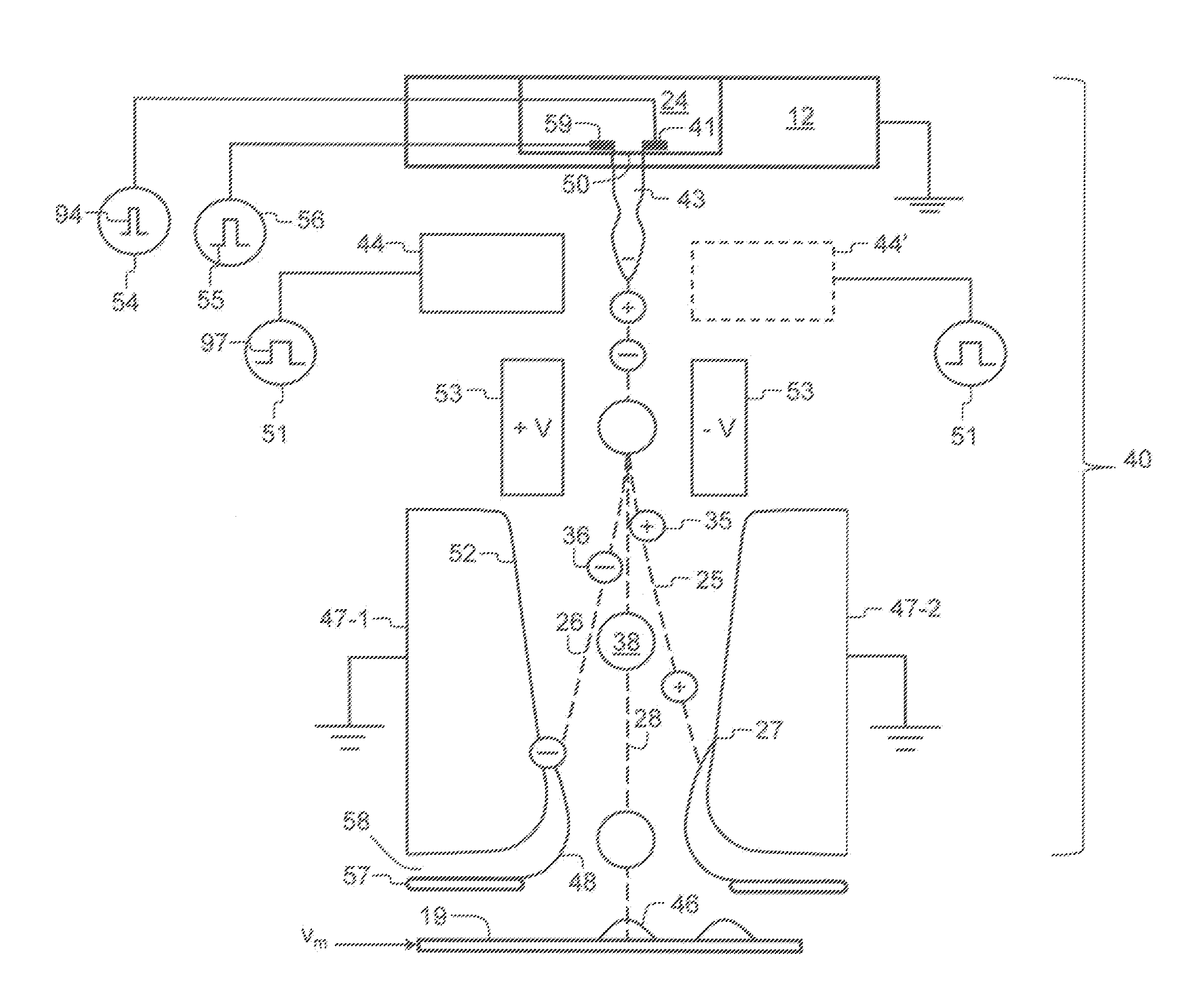
[0031]As described herein, example embodiments of the present invention provide a printhead or printhead components typically used in inkjet printing systems. In such systems, the liquid is an ink for printing on a recording media. However, o...


PUM


Abstract

An apparatus and method of ejecting liquid drops includes modulating a liquid jet to cause it to break off into drop clusters, including first and second drops traveling along a path, separated on average by a drop cluster period. An input image data independent charging waveform of a charging device includes a period that is equal to the cluster period and first and second voltage states having opposing polarities. The charging device produces first and second charge states on the first and second drops, respectively, of each cluster. The first and second drops are deflected away from the path toward first and second catchers, respectively. Relative velocity of drops of a selected drop cluster is modulated in response to input print data causing the drops to form a merged drop traveling along the path having a third charge state that prevents it from being deflected to either catcher.

Description

CROSS REFERENCE TO RELATED APPLICATIONS[0001]Reference is made to commonly-assigned, U.S. patent application Ser. No. 13 / 530,161, entitled “CONTROLLING DROP CHARGE USING DROP MERGING DURING PRINTING”, filed Jun. 22, 2012.FIELD OF THE INVENTION[0002]This invention relates generally to the field of digitally controlled printing systems, and in particular to continuous printing systems in which a liquid stream breaks into drops some of which are electrostatically deflected.BACKGROUND OF THE INVENTION[0003]Ink jet printing has become recognized as a prominent contender in the digitally controlled, electronic printing arena because, e.g., of its non-impact, low-noise characteristics, its use of plain paper and its avoidance of toner transfer and fixing. Ink jet printing mechanisms can be categorized by technology as either drop on demand ink jet (DOD) or continuous ink jet (CIJ).[0004]The first technology, “drop-on-demand” ink jet printing, provides ink drops that impact upon a recording...

Claims


Application Information

Patent Timeline
Patent Type & Authority Patents(United States)
IPC IPC(8): B41J2/185B41J2/07B41J2/115
CPCB41J2/115B41J2002/033B41J29/38B41J2/09B41J2/04B41J2/03B41J2/185B41J2/085
Inventor MARCUS, MICHAEL A.KATERBERG, JAMES A.PANCHAWAGH, HRISHIKESH V.
Owner EASTMAN KODAK CO
Why Eureka
Try Eureka