
Method and system for diagnosing a fault or open circuit in a network

a network and fault technology, applied in the field of network fault or open circuit diagnosis, can solve the problems of inability to physically inspect the transmission line, inability to carry out physical visual inspection, and inability to meet the requirements of the network data bus

Active Publication Date: 2014-04-15
DEERE & CO
View PDF25 Cites 16 Cited by
  • Summary
  • Abstract
  • Description
  • Claims
  • Application Information

AI Technical Summary

Benefits of technology

The patent describes a way to diagnose problems in a network, like a car's network, that uses a data bus. A test signal is injected into the network data bus and the resulting signal is measured using an analog-to-digital converter. This way, any faults in the network can be easily detected.

Problems solved by technology

If the transmission line is cut or damaged, communications over the network data bus can be impaired, intermittent or absent.
Physical visual inspection of the transmission line may not be practical or possible where the cable is routed through conduit, sheathing, frame members, unibody vehicle structures, body panels, or other equipment structures.

Method used


Image

  • Method and system for diagnosing a fault or open circuit in a network
  • Method and system for diagnosing a fault or open circuit in a network
  • Method and system for diagnosing a fault or open circuit in a network

Examples


Embodiment Construction

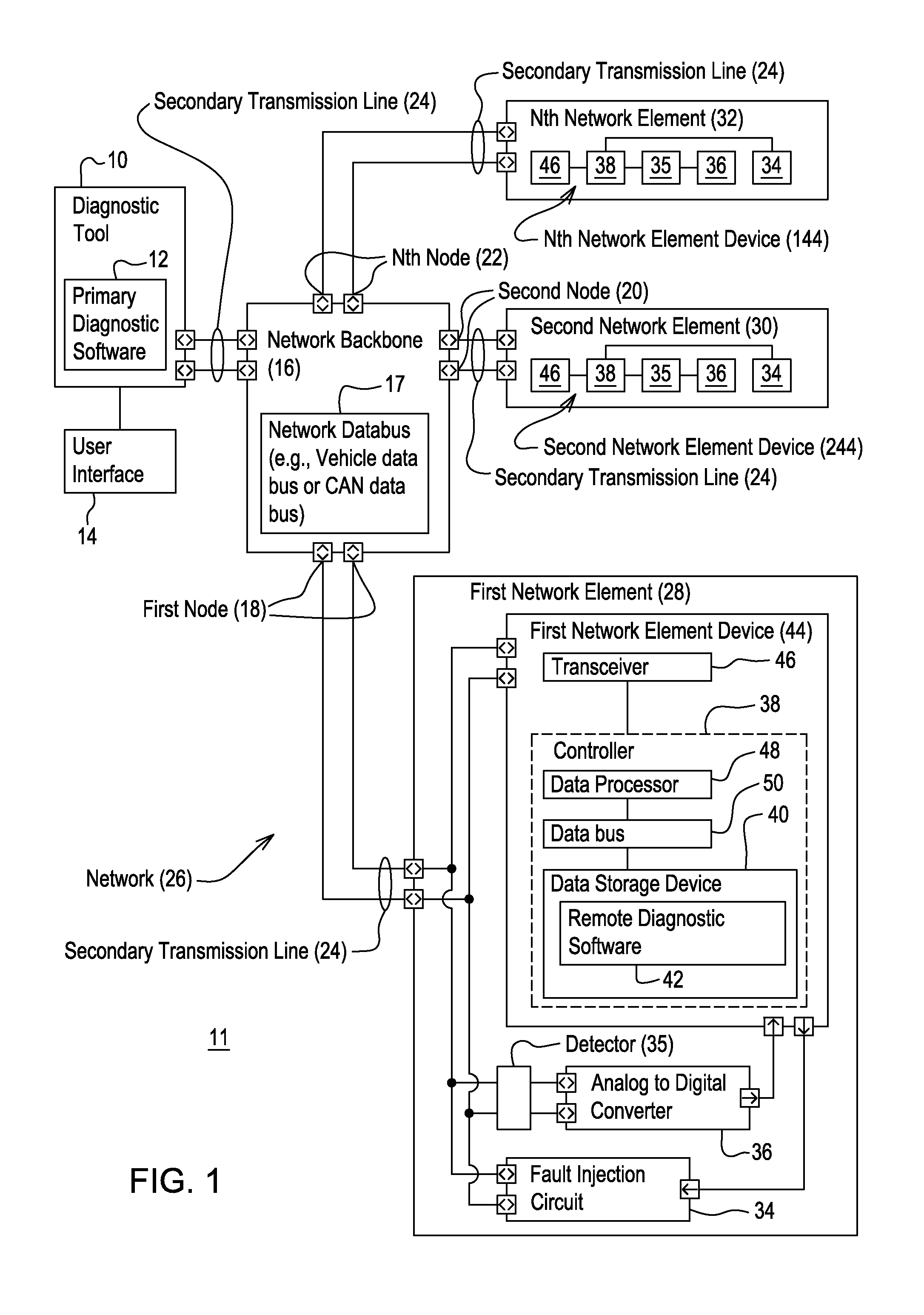
[0011]In FIG. 1, in accordance with one embodiment, a system 11 is configured for diagnosing a fault or open circuit in a network 26. The network 26 may refer to a vehicle network, an implement network, a subnet, a subnet of vehicle network, a subnet of an implement network, or any other network. The system 11 comprises a network 26, a network backbone 16 (e.g., network data bus 17), one or more network elements (28, 30, 32), a fault injection circuit 34, a detector 35, and analog-to-digital converter 36, and a diagnostic tool 10. At least one network element (28, 30, 32) comprises a fault injection circuit 34, a detector 35 and an analog-to-digital converter 36. The diagnostic tool 10 is coupled to the data network 26. The diagnostic tool 10 and the network elements (28, 30, 32) are capable of communicating over the network data bus 17, network backbone 16, or an auxiliary data bus of the network 26.

[0012]In one embodiment, the network 26 comprises a network backbone 16 and one or ...


PUM


Abstract

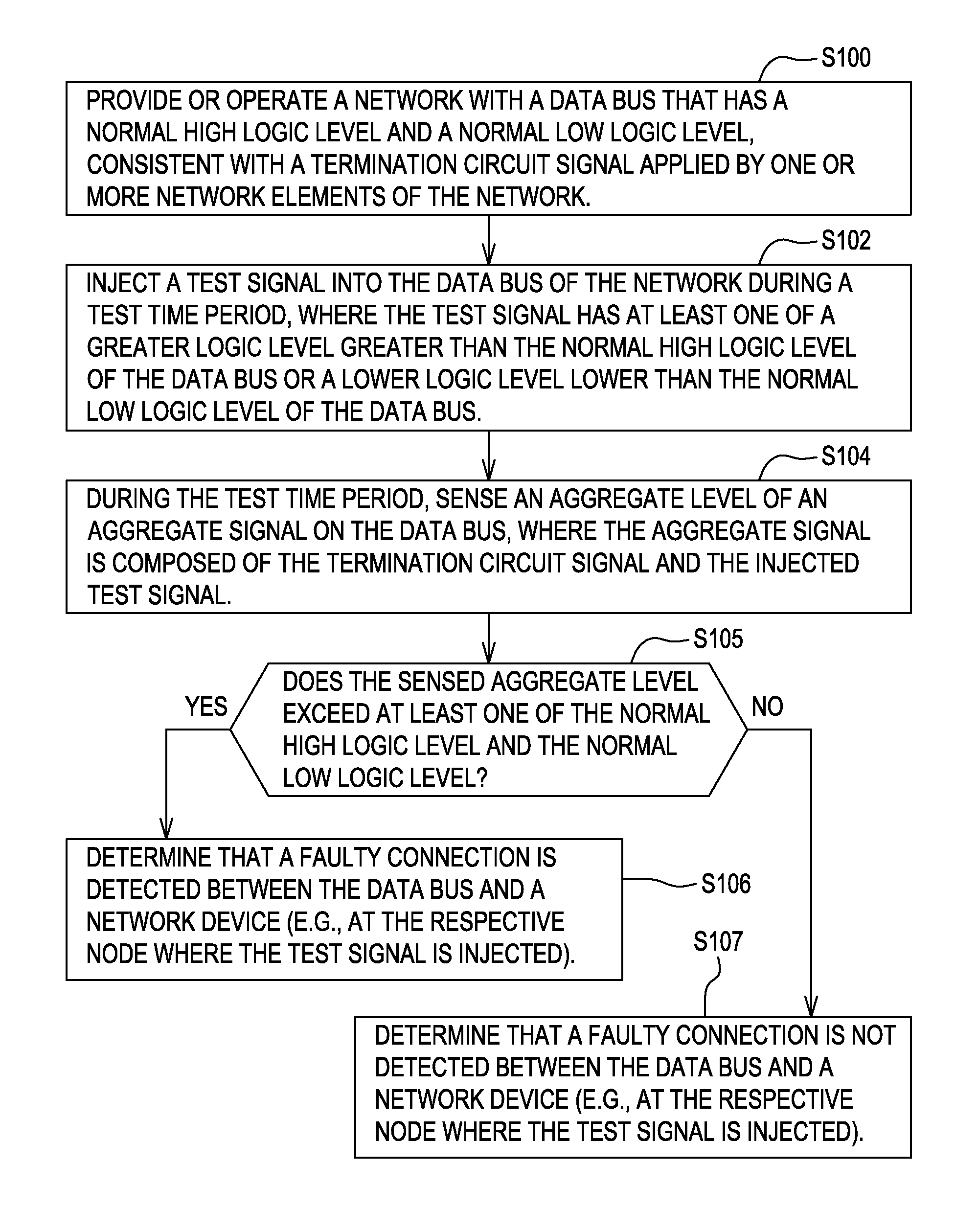
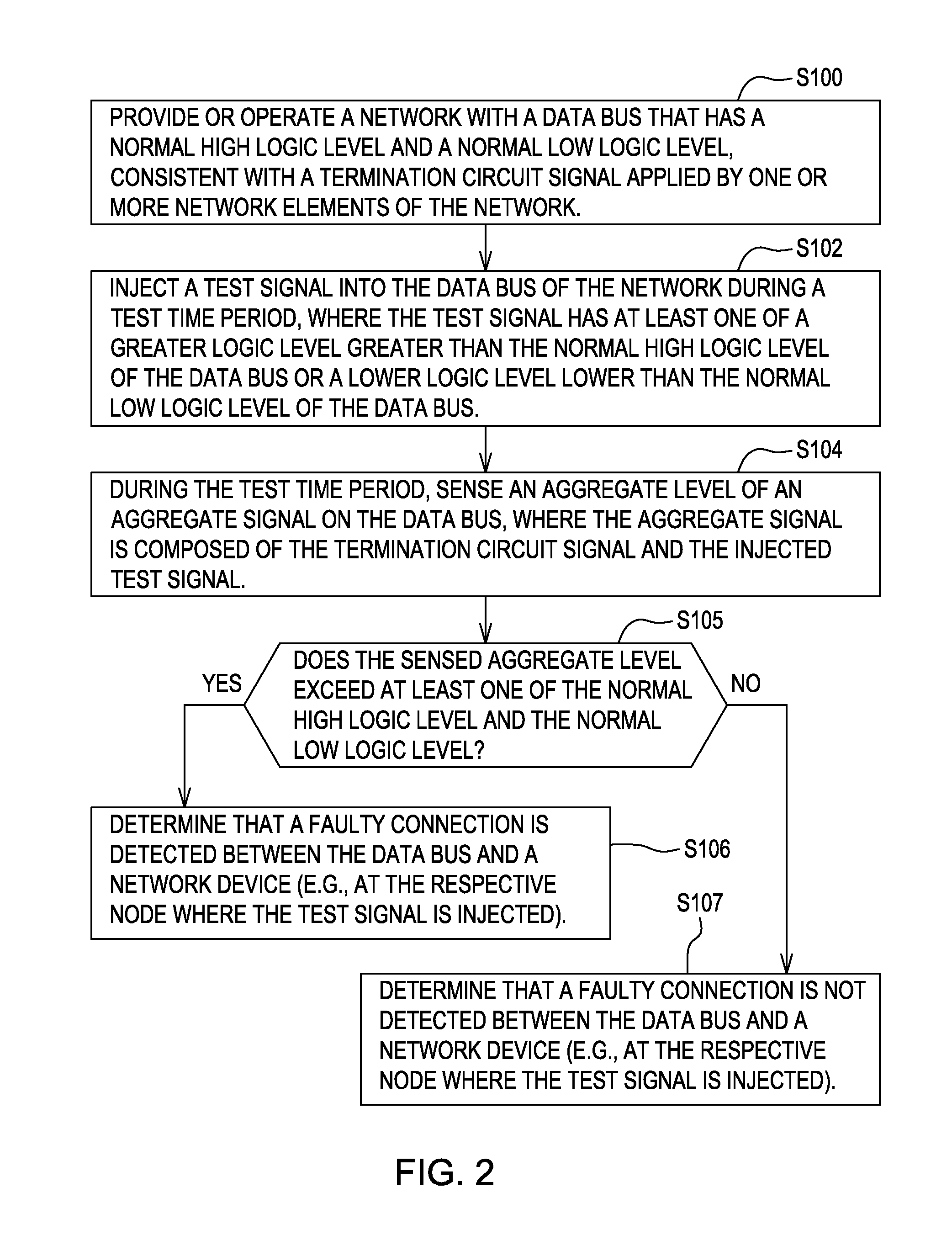
A fault injection circuit injects a test signal into a data bus with a normal high logic level and a normal low logic level. The test signal has a greater logic level greater than the normal high logic level of the data bus or a lower logic level lower than the normal low logic level of the data bus. An analog-to-digital converter is coupled to a voltage level detector for sensing an aggregate level of an aggregate signal on the data bus. The aggregate signal is composed of the termination circuit signal and the test signal. A diagnostic tool determines whether a faulty connection between the data bus and a network device exists, where the sensed aggregate level exceeds at least one of the normal high logic level and the normal low logic level.

Description

[0001]This document claims priority based on U.S. provisional application Ser. No. 61 / 424,926, filed on Dec. 20, 2010 and entitled METHOD AND SYSTEM FOR DIAGNOSING A FAULT OR OPEN CIRCUIT IN A NETWORK, under 35 U.S.C. 119(e).FIELD OF THE INVENTION[0002]This invention relates to a method and system for diagnosing a fault or open circuit in a network.BACKGROUND[0003]In the prior art, a vehicle or equipment may be configured with a controller area network (CAN) data bus or another network data bus that supports communication between controllers and other network elements. The vehicle data bus communicates signals over a transmission line, such as one or more twisted pairs of wire or a coaxial cable, for example. If the transmission line is cut or damaged, communications over the network data bus can be impaired, intermittent or absent. Physical visual inspection of the transmission line may not be practical or possible where the cable is routed through conduit, sheathing, frame members...

Claims


Application Information

Patent Timeline
Patent Type & Authority Patents(United States)
IPC IPC(8): G06F11/00H04L69/40
CPCH04L2012/40215H04L43/50H04L41/0609H04L12/2697H04L12/40169
Inventor SMART, DAVID C.SCHLICHTMANN, MICHAEL R.LANDMAN, RONALD G.
Owner DEERE & CO
Learn More