

Method for driving a cooling fan within an electronic display
a technology of electronic display and cooling fan, which is applied in the direction of static indicating device, process and machine control, instruments, etc., can solve the problems of increasing the cooling difficulty of internal display components, and increasing the cost of cooling. the effect of the display
- Summary
- Abstract
- Description
- Claims
- Application Information
AI Technical Summary
Benefits of technology
Problems solved by technology
Method used
Image

Examples
Embodiment Construction
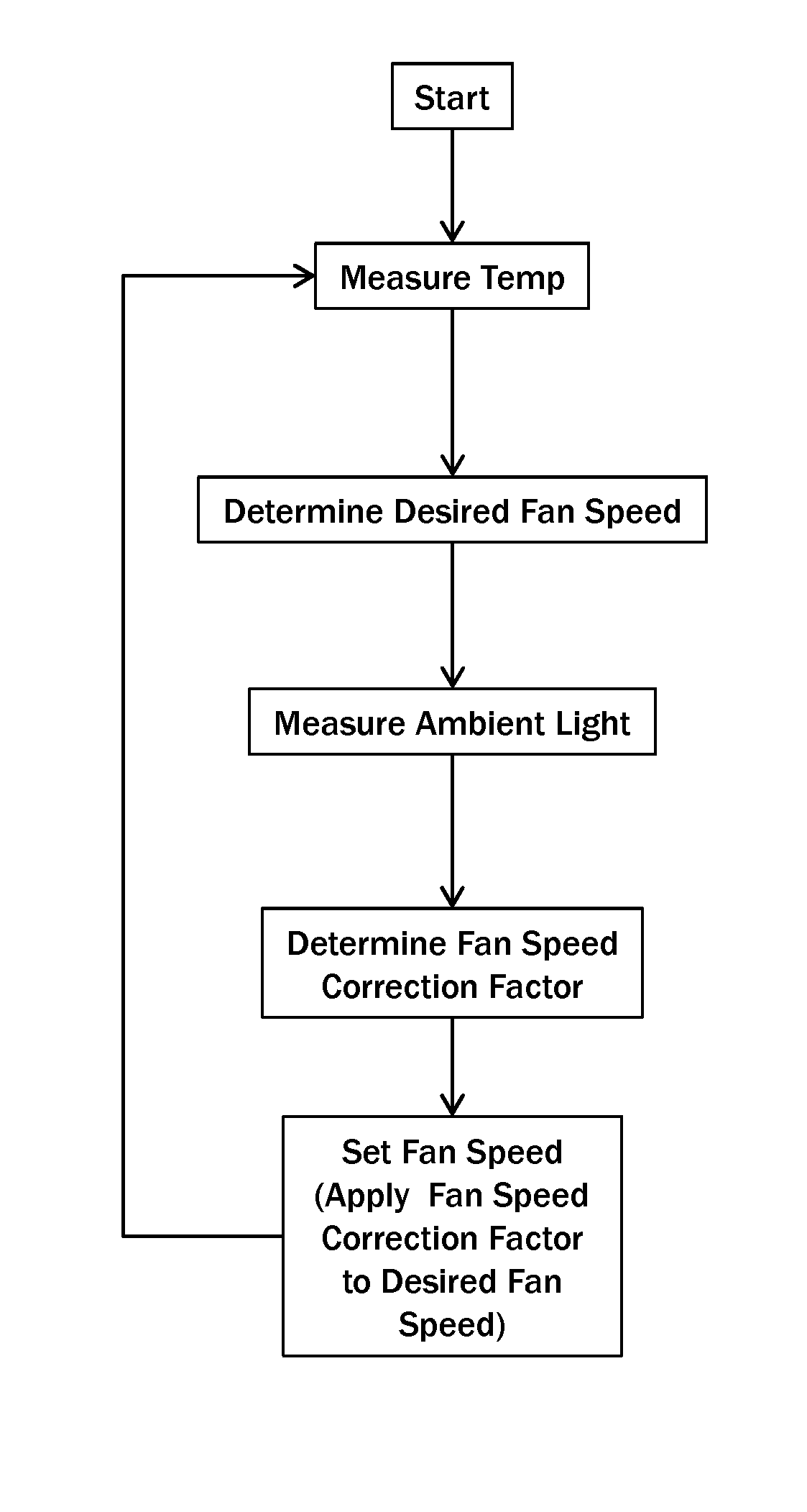
[0008]Thus, it has been discovered that the exposure of the front display surface and / or housing to sunlight is a typical cause of many internal temperature rises within the display. This discovery has led to a potential relationship between a measurement of the amount of ambient light and a potential temperature rise within the display. The exemplary embodiments herein use the data from an ambient light sensor in order to apply a correction factor to the actual temperature data and / or the fan speeds in order to anticipate a rise in temperature and reduce its impact on the display.
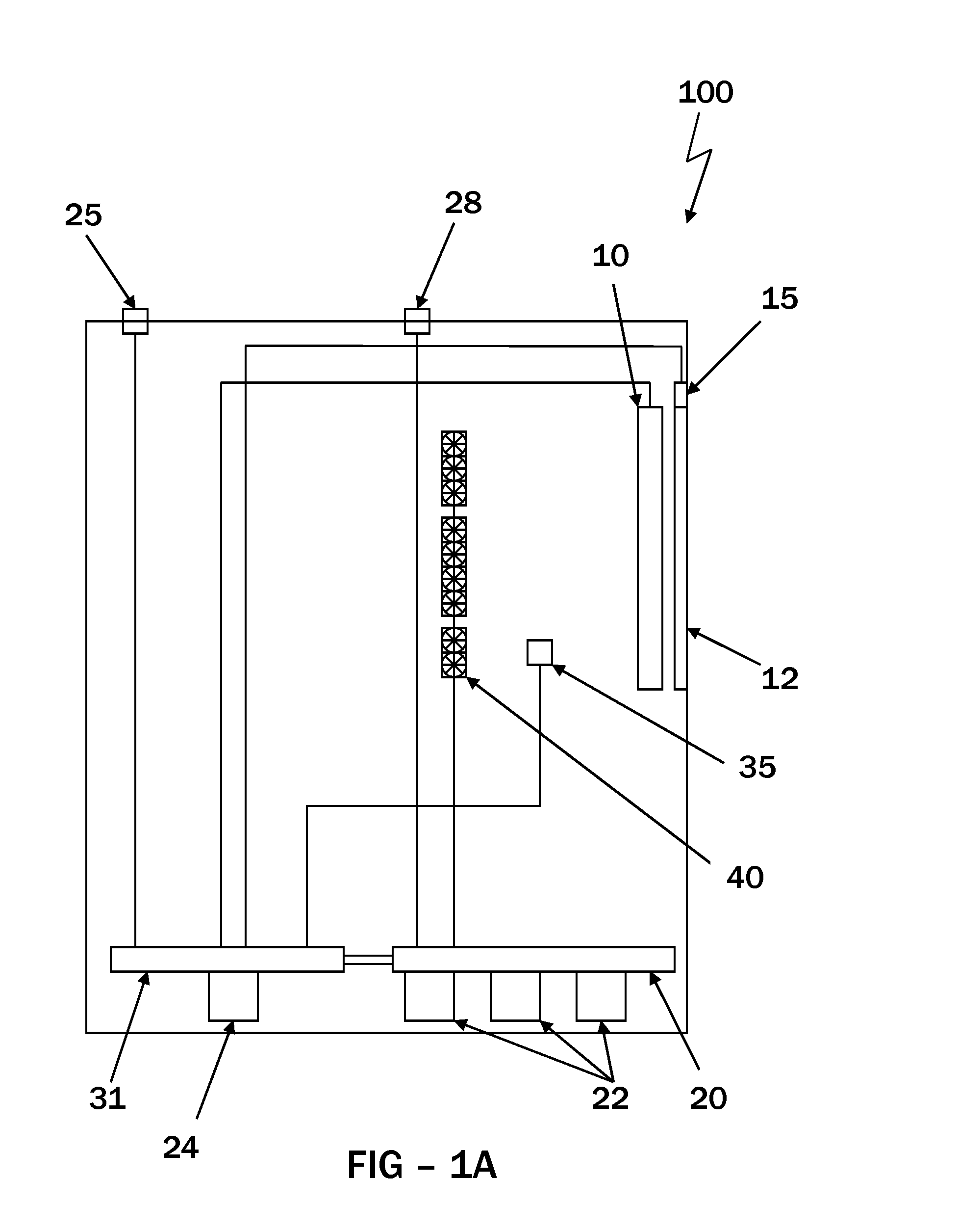
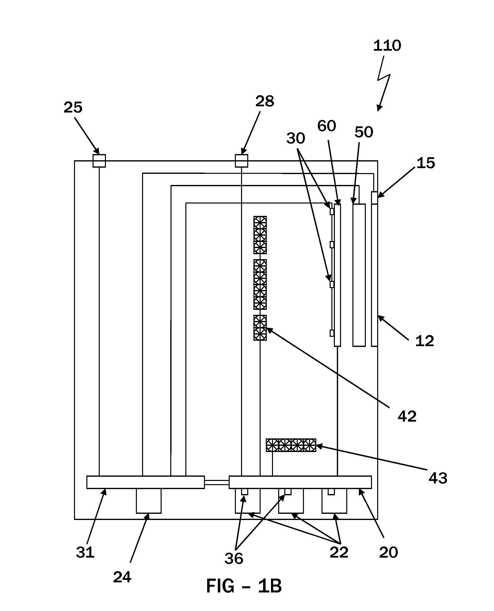
[0009]The temperature sensors may be placed in one or more places within the display. Typically, the temperature sensors are placed in close proximity to one or more components that are known to increase in heat during operation (especially in high ambient temperatures and / or direct sunlight). In some embodiments, the temperature sensors are placed within or near the image assembly, on or in close proximit...
PUM
 Abstract
Description
Claims
Application Information