Magnetostrictive torque sensor and electrical power steering device

a torque sensor and torque sensor technology, applied in the direction of force/torque/work measurement apparatus, instruments, transportation and packaging, etc., can solve problems such as conductivity failure, and achieve the effect of accurately detecting torque, less susceptible to alternating magnetic fields, and no noise generation

Active Publication Date: 2014-04-22
HONDA MOTOR CO LTD
View PDF15 Cites 11 Cited by
  • Summary
  • Abstract
  • Description
  • Claims
  • Application Information

AI Technical Summary

Benefits of technology

[0012]It is an object of the present invention to provide a magnetostrictive torque sensor, which will solve the above problems, and an electrically operated power steering apparatus, which incorporates a magnetostrictive torque sensor therein for imparting an improved steering sensation.
[0031]With the electrically operated power steering apparatus according to the present invention, even if alternating magnetic fields are generated by a peripheral device, since such alternating magnetic fields do not pass through the steering shaft member, noise is not generated and vibrations are reduced. Consequently, the electrically operated power steering apparatus allows the driver to experience a smooth steering sensation in a quiet and highly responsive manner. Also, the steering torque sensor does not adversely affect other sensors on and around the steering shaft member, such as a steering angle sensor, etc.

Problems solved by technology

At this time, the leading and trailing ends of the first coil and the second coil may possibly be brought into contact with the aluminum alloy housing, resulting in a conduction failure.

Method used


Image

  • Magnetostrictive torque sensor and electrical power steering device
  • Magnetostrictive torque sensor and electrical power steering device
  • Magnetostrictive torque sensor and electrical power steering device

Examples


first embodiment

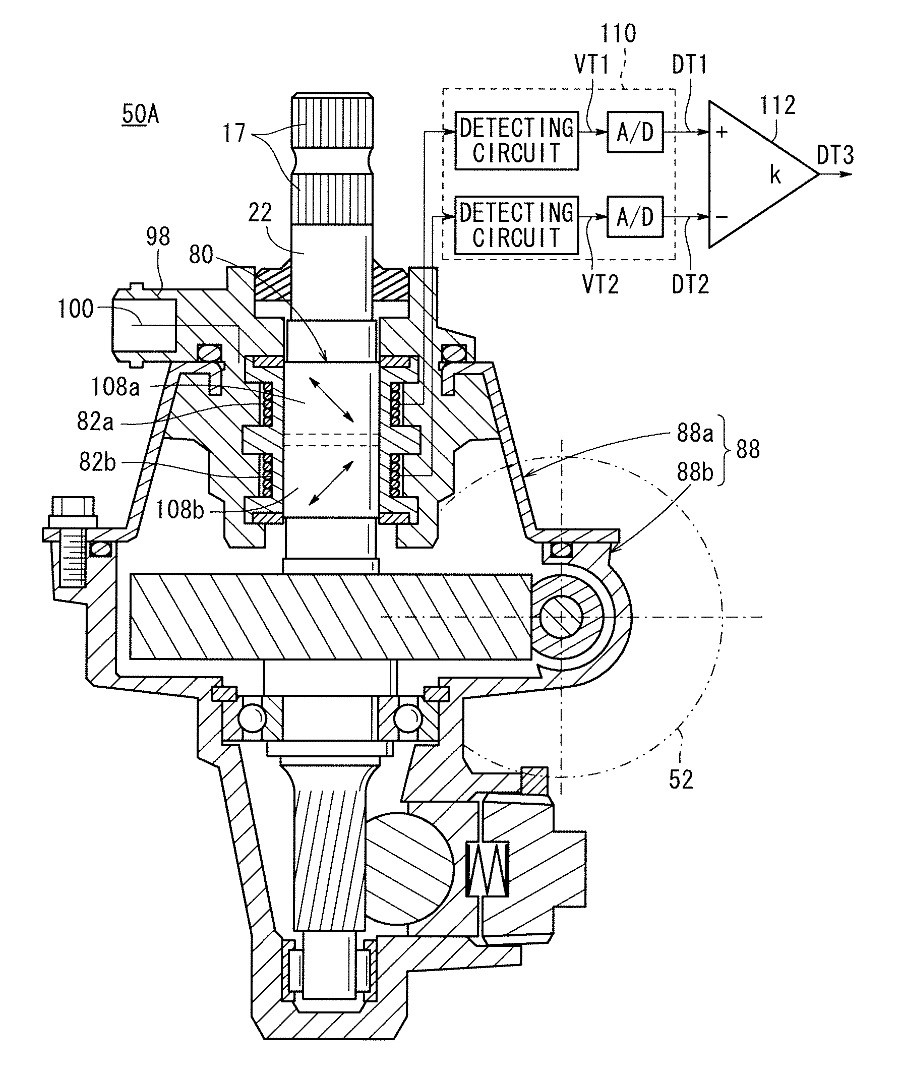
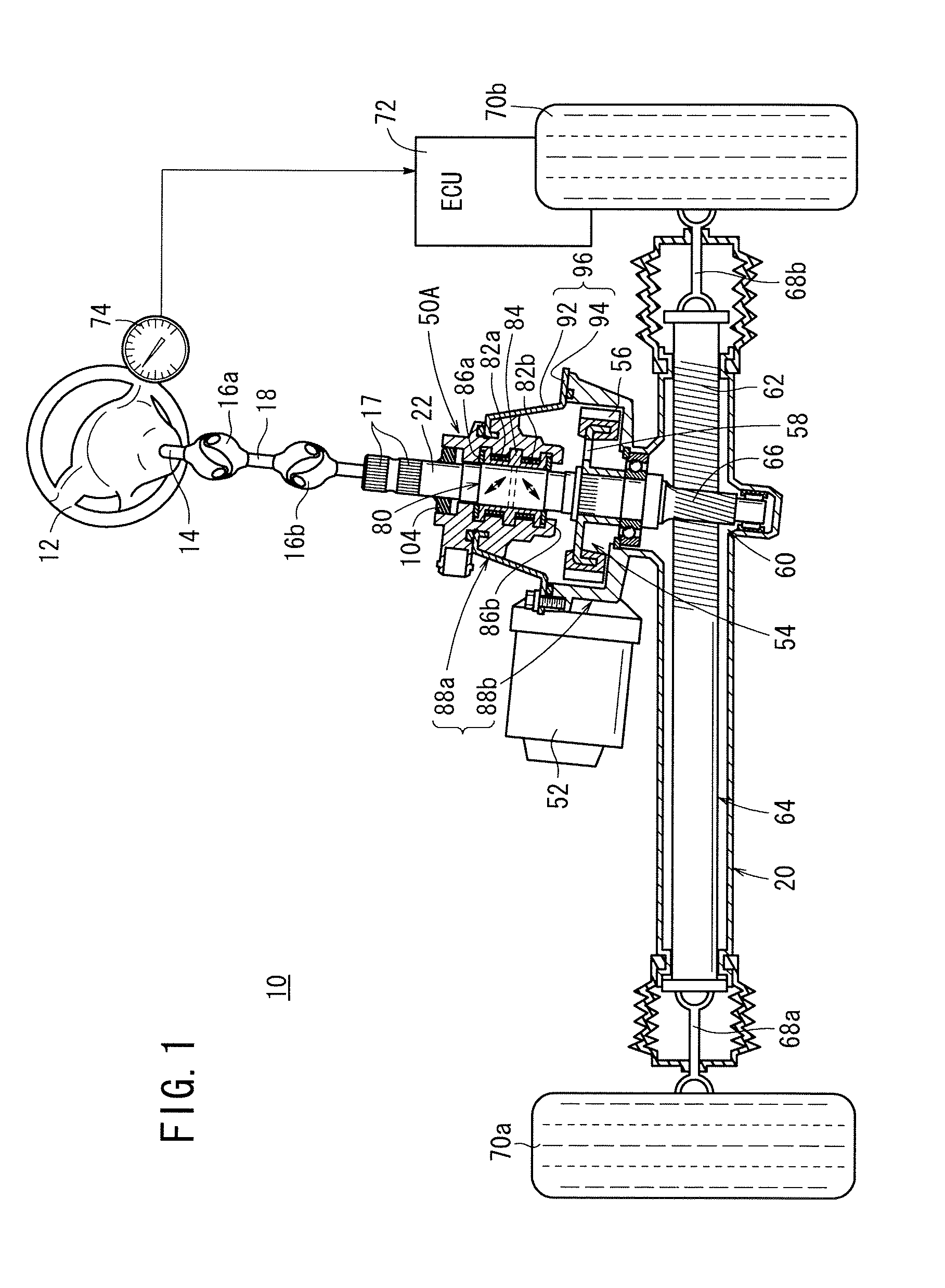
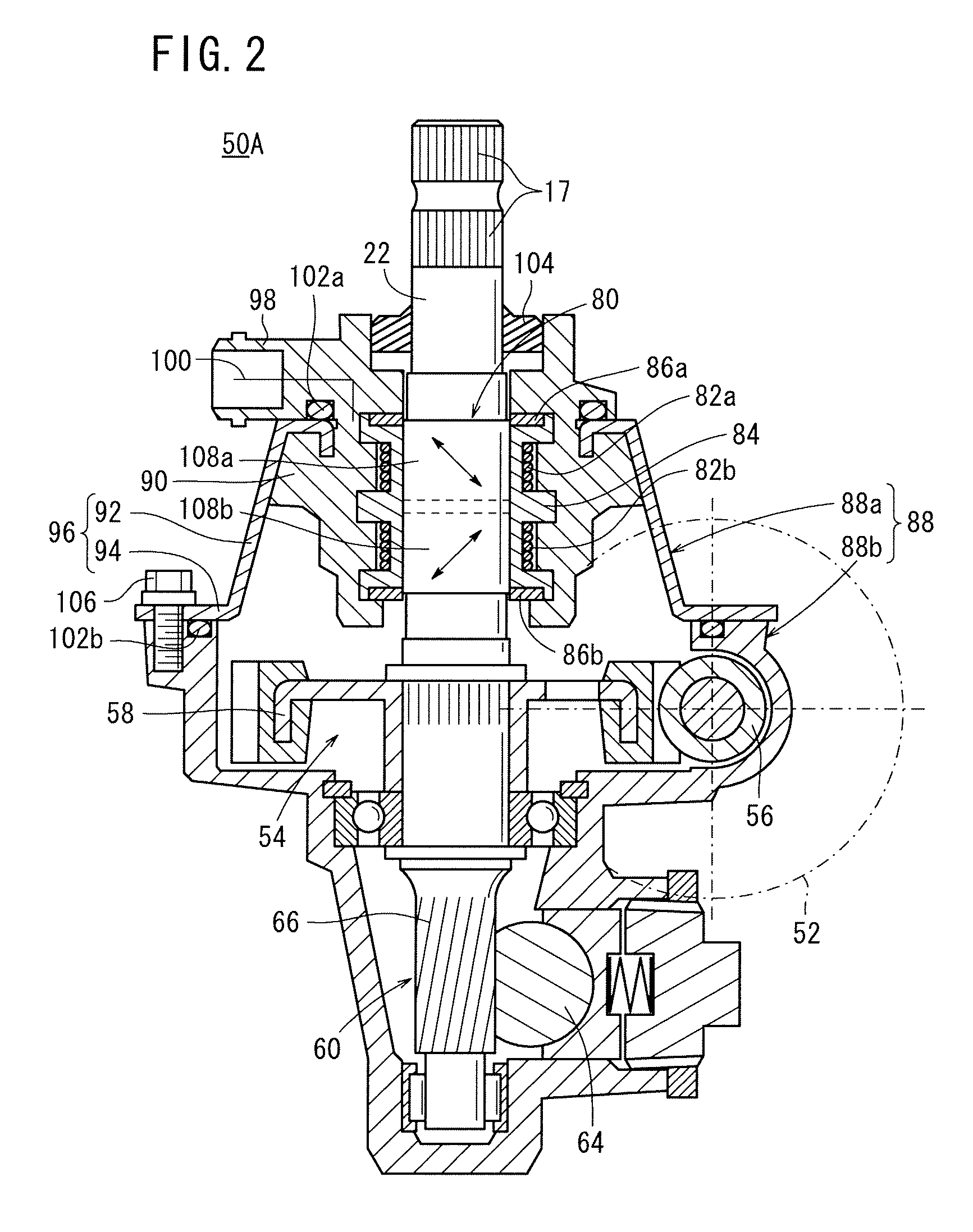
[0076]The steering gearbox 20 includes the steering shaft member 22 (shaft member), a magnetostrictive torque sensor (hereinafter referred to as a “first torque sensor 50A”) which serves as a steering torque sensor for detecting a steering torque applied by the driver, a motor 52 (e.g., a brushless motor) for assisting a steering action made by the driver, a speed reducer 54 (a worm 56 and a worm wheel 58; see FIG. 2) for boosting rotational torque generated by the motor 52, a rack and pinion gear 60, and a rack shaft 64 having formed thereon a rack gear 62 of the rack and pinion gear 60.

[0077]The steering shaft member 22 has one end coupled to the steering wheel 12 by the steering shaft 14, the first universal joint 16a, the intermediate shaft 18, and the second universal joint 16b. The other end of the steering shaft member 22 serves as a pinion gear 66 of the rack and pinion gear 60.

[0078]A rotational torque, which is boosted by the speed reducer 54, is converted into an axial t...

second embodiment

[0168]A magnetostrictive torque sensor (hereinafter referred to as a “second torque sensor 50B”) will be described below with reference to FIGS. 29 and 30.

[0169]The second torque sensor 50B is substantially of the same structure as the first torque sensor 50A described above, but differs therefrom as to the structure of the metal member 96, which includes the tubular part 92 and the flange 94.

[0170]The metal member 96 is not encased within the resin part 90. The metal member 96, which is substantially L-shaped in vertical cross section, is mounted in position with an upper end face thereof held against a flange that includes the lower surface of the connector 98 of the resin part 90, the tubular part 92 is pressed against the resin part 90, and the flange 94 is fastened by bolts 106 to the second housing member 88b. The tubular part 92 is inclined slightly with respect to the axial direction of the steering shaft member 22, as viewed in vertical cross section. A ring-shaped adjustm...


PUM

PropertyMeasurementUnit
thicknessaaaaaaaaaa
thicknessaaaaaaaaaa
thicknessaaaaaaaaaa

Abstract

Disclosed are a magnetostrictive torque sensor and an electrical power steering device, wherein a first torque sensor has: one magnetostrictive film provided on a steering shaft; a first coil and a second coil that detect changes in the magnetic characteristics of the magnetostrictive film; and a first housing that contains, at least, the steering shaft, the magnetostrictive film, the first coil, and the second coil. The first housing has a resin part, a cylindrical part made of a metal that is soft magnetic, and a flange part made of a metal that is soft magnetic. The resin part, the cylindrical part, and the flange part are formed as a unit.

Description

TECHNICAL FIELD[0001]The present invention relates to a magnetostrictive torque sensor for detecting torque based on a change in magnetic properties due to magnetostriction, and an electrically operated power steering apparatus including such a magnetostrictive torque sensor therein.BACKGROUND ART[0002]One known type of contactless torque sensor is a magnetostrictive torque sensor for detecting torque based on a change in magnetic properties due to magnetostriction. Such a magnetostrictive torque sensor is used to detect the steering torque of an automotive steering apparatus (see Japanese Laid-Open Patent Publication No. 2004-309184).[0003]The magnetostrictive torque sensor of the type described above comprises two magnetostrictive films (a first magnetostrictive film and a second magnetostrictive film) mounted on a shaft and having different magnetic anisotropic properties, and a first shaft and a second shaft, which are disposed in confronting relation to the first magnetostricti...

Claims


Application Information

Patent Timeline
Patent Type & Authority Patents(United States)
IPC IPC(8): G01L3/02
CPCG01L5/221G01L3/102G01L3/103B62D6/10
Inventor SHIMIZU, YASUOYONEDA, ATSUHIKOARIMURA, YUTAKAONIWA, YOSHIHIRO
Owner HONDA MOTOR CO LTD
Why Eureka
Try Eureka