Multi-link, adjustable-stroke type engine
a multi-link, adjustable-stroke technology, applied in the direction of machines/engines, crankshafts, auxiliaries, etc., can solve the problems of increased friction sound, engine noise that is undetectable, and parts that differ in a very complicated manner, so as to reduce gear rattling noise and gear meshing noise.
- Summary
- Abstract
- Description
- Claims
- Application Information
AI Technical Summary
Benefits of technology
Problems solved by technology
Method used
Image
Examples
first embodiment
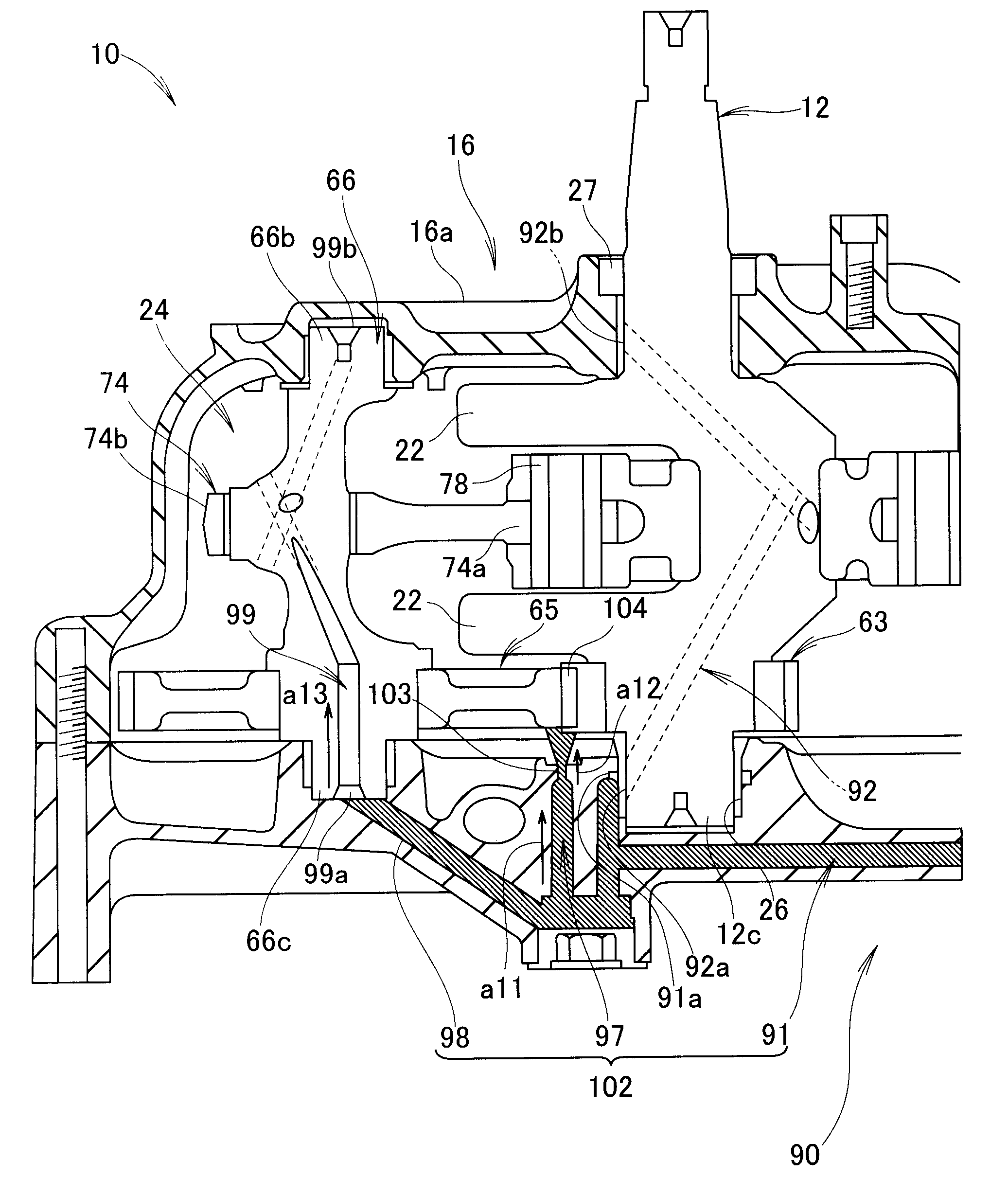
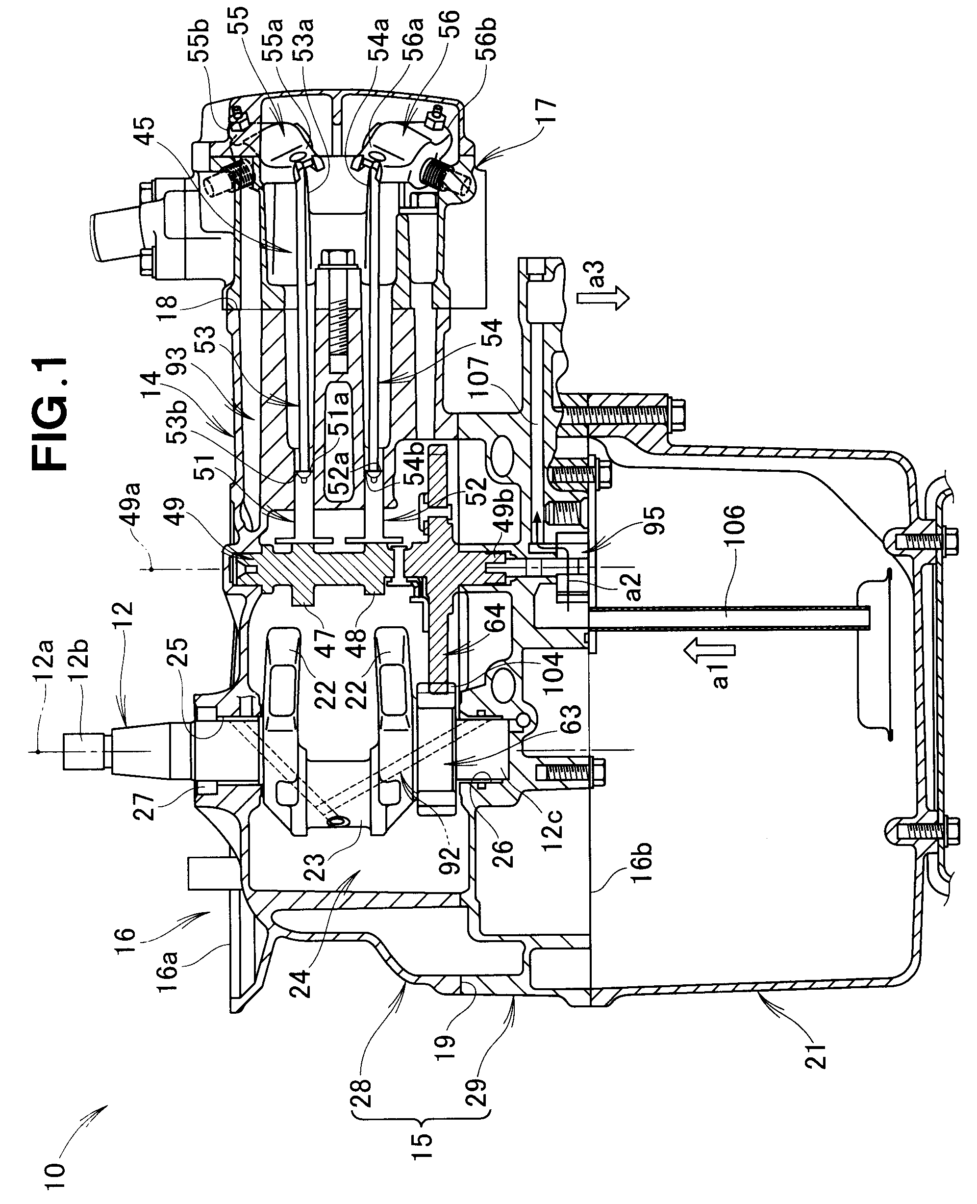
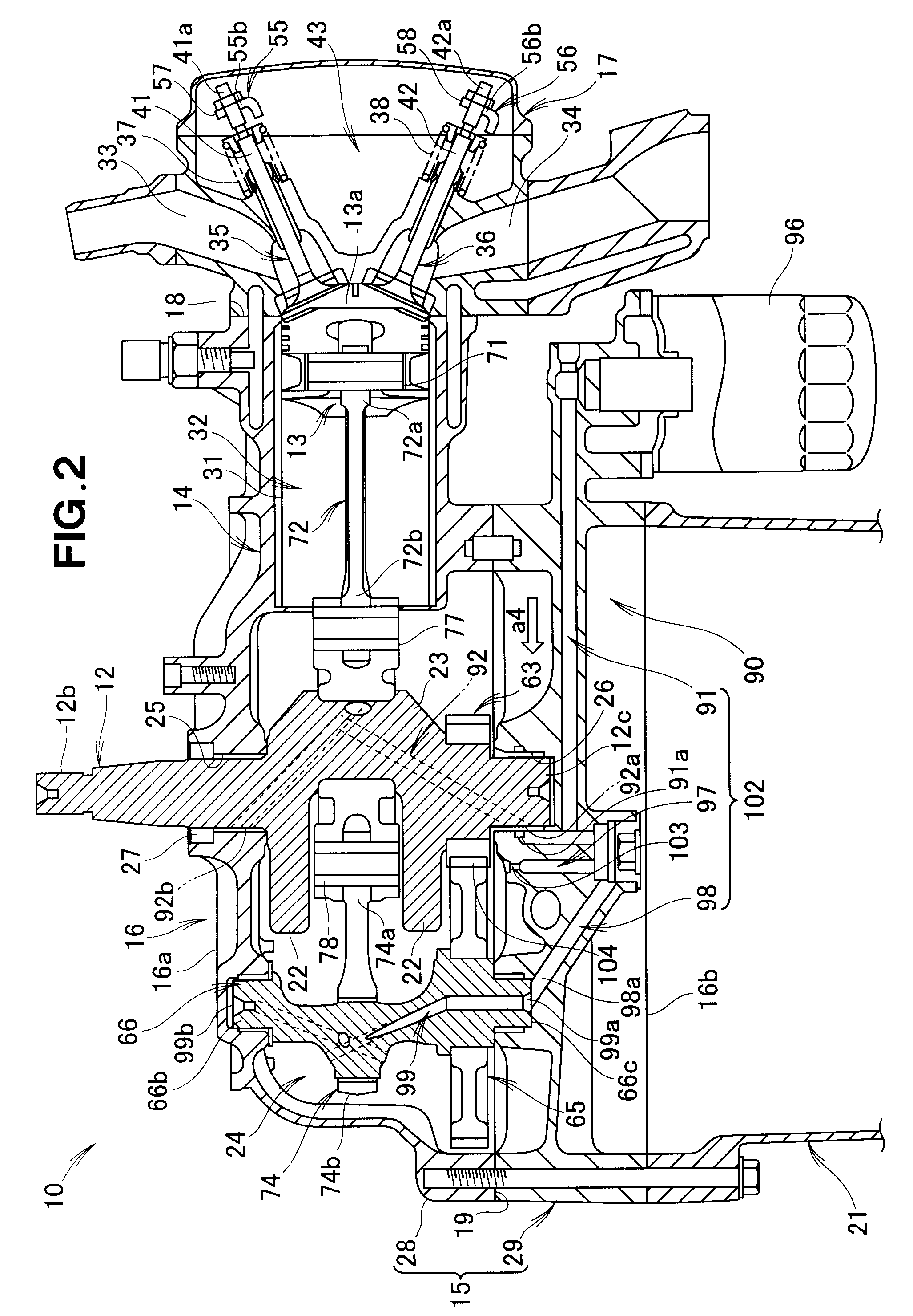
[0024]As shown in FIGS. 1 to 5, a first embodiment of an engine 10 of the present invention is an air-cooling type single-cylinder engine for use, for example, in working machines. More specifically, the engine 10 is a vertical, multi-link, adjustable-stroke type engine in which the axis line 12a of a crankshaft 12 is oriented or extending in a substantially vertical direction and in which intake and compression strokes of a piston 13 are adjustable. For convenience of description, the engine 10 will hereinafter sometimes be referred to also as “vertical engine 10”, “multi-link, adjustable-stroke type engine 10” or “vertical, multi-link, adjustable-stroke type engine 10”.
[0025]The engine 10 includes an outer envelope comprising: a cylinder barrel (or engine block) 16 having formed therein a cylinder or cylinder block 14 for reciprocatively guiding the piston 13, and a crankcase 15 for rotatably supporting a crankshaft 12; a cylinder head 17 closing a cylinder-side opening 18 of the ...
second embodiment
[0065]FIG. 7 shows a second embodiment of the present invention provided with a lubrication device 120 that is a modification of the lubrication device 90 shown in FIGS. 1 to 6. The second embodiment is generally similar to the above-described first embodiment, except for the lubrication device 120. Namely, the lubrication device 120 in the second embodiment is different from the lubrication device 90 in the first embodiment in that a crank-side shaft-end supply opening 121b for supplying lubricating oil to the lower shaft end portion 12c of the crankshaft 12 is added to a first lubricating oil passageway 121 corresponding to the first lubricating oil passageway 91 of the above-described first embodiment.
[0066]Namely, the lubrication device 120 includes: a first lubricating oil passageway 121 for supplying lubricating oil to the lower bearing 26 of the crankshaft 12; a gear lubricating oil passageway 127 (corresponding to the gear lubricating oil passageway 97 of the above-described...
third embodiment
[0072]FIG. 8 shows a third embodiment of the present invention provided with a lubrication device 140 that is another modification of the lubrication device 90 shown in FIGS. 1 to 6. The third embodiment is generally similar to the above-described first embodiment, except for the lubrication device 140. The lubrication device 140 is different from the lubrication device 90 in that it does not include the shaft-end oil output opening 99b through which lubricant oil of the upper end portion 66b of the eccentric shaft 66 is output, but includes a peripheral oil output opening 149c.
[0073]Namely, the lubrication device 140 in the third embodiment includes: a first lubricating oil passageway 141 (corresponding to the first lubricating oil passageway 91 of the above-described first embodiment) for supplying lubricating oil to the lower bearing 26 of the crankshaft 12; a gear lubricating oil passageway 147 (corresponding to the gear lubricating oil passageway 97 of the above-described firs...
PUM
 Abstract
Description
Claims
Application Information
 - R&D
- Intellectual Property
- Life Sciences
- Materials
- Tech Scout
- Unparalleled Data Quality
- Higher Quality Content
- 60% Fewer Hallucinations
Browse by: Latest US Patents, China's latest patents, Technical Efficacy Thesaurus, Application Domain, Technology Topic, Popular Technical Reports.
© 2025 PatSnap. All rights reserved.Legal|Privacy policy|Modern Slavery Act Transparency Statement|Sitemap|About US| Contact US: help@patsnap.com


