
Adaptable therapeutic, diagnostic or surgical guide

a technology of therapeutic and diagnostic guide, applied in the field of medical science, can solve the problems of guide not having a unique fit, guide may not fit in certain regions, image may be unclear in certain regions,

Active Publication Date: 2014-04-22
MATERIALISE NV
View PDF25 Cites 7 Cited by
  • Summary
  • Abstract
  • Description
  • Claims
  • Application Information

AI Technical Summary

Benefits of technology

The present invention proposes a new design for medical guides that can accurately fit for a targeted area of a patient and allow precise targeting and control of surgical interventions. The invention uses a mechanical guiding system based on medical images. The elastic elements in the guide ensure that the surface of the patient remains in contact and can also provide an indicator function. The fitting data can be displayed using optical navigation or other measuring devices. This reduces the risk of using a guide in an improper position and allows the surgeon to take into account the contact surfaces of the guide not visible along the outer border or windows.

Problems solved by technology

If the patient's anatomy on which the guide was designed changes during this waiting period, the guide will not have a unique fit.
A second limitation of using a static, image-based guide is that the images may be unclear in certain regions.
This has an effect in two ways: firstly, incorrect planning based on unclear anatomic landmarks is possible, for example a cut is deeper than expected; and secondly, the resulting guide does not fit in certain regions.
With the static guide models complete surface matching is often not possible.
Surface hinges are most detrimental to the guide fit since they limit the remaining surface contact and the unique fit is then impossible.
However, with less surface contact available, the likelihood of an improper fit even increases.
This improper fit can lead to incorrect surgical results since the active elements are in a different position than what was pre-operatively planned.
A third limitation of the current surgical guides is that they transfer a surgical plan that is only based on the images and intraoperative visual information.
The result is that multiple surgical acts are difficult to perform in a guided way and hence, in fact, finally rely on mental navigation once a difference from the pre-planned patient anatomy is determined.
These adjustable guides also have the same risks as static guides in that they can be misplaced on the anatomic surface since they use a static surface contact.
If this occurs, the surgeon can no longer trust any pre-operative planning since the reference position is inaccurate.
Thus, the adjustment can be needed but is problematic for the same reasons as those that affect the fit of guides, but also due to the fact that the position of the body of the patient may be quite different on the operation table compared to the time when the image scans were taken.
However imaging for long periods during an operation, adds its own risks for the patient and the medical staff, e.g. radiation exposure.

Method used


Image

  • Adaptable therapeutic, diagnostic or surgical guide
  • Adaptable therapeutic, diagnostic or surgical guide
  • Adaptable therapeutic, diagnostic or surgical guide

Examples


Embodiment Construction

[0052]The present invention will be described with respect to particular embodiments and with reference to certain drawings but the invention is not limited thereto but only by the claims. The drawings described are only schematic and are non-limiting.

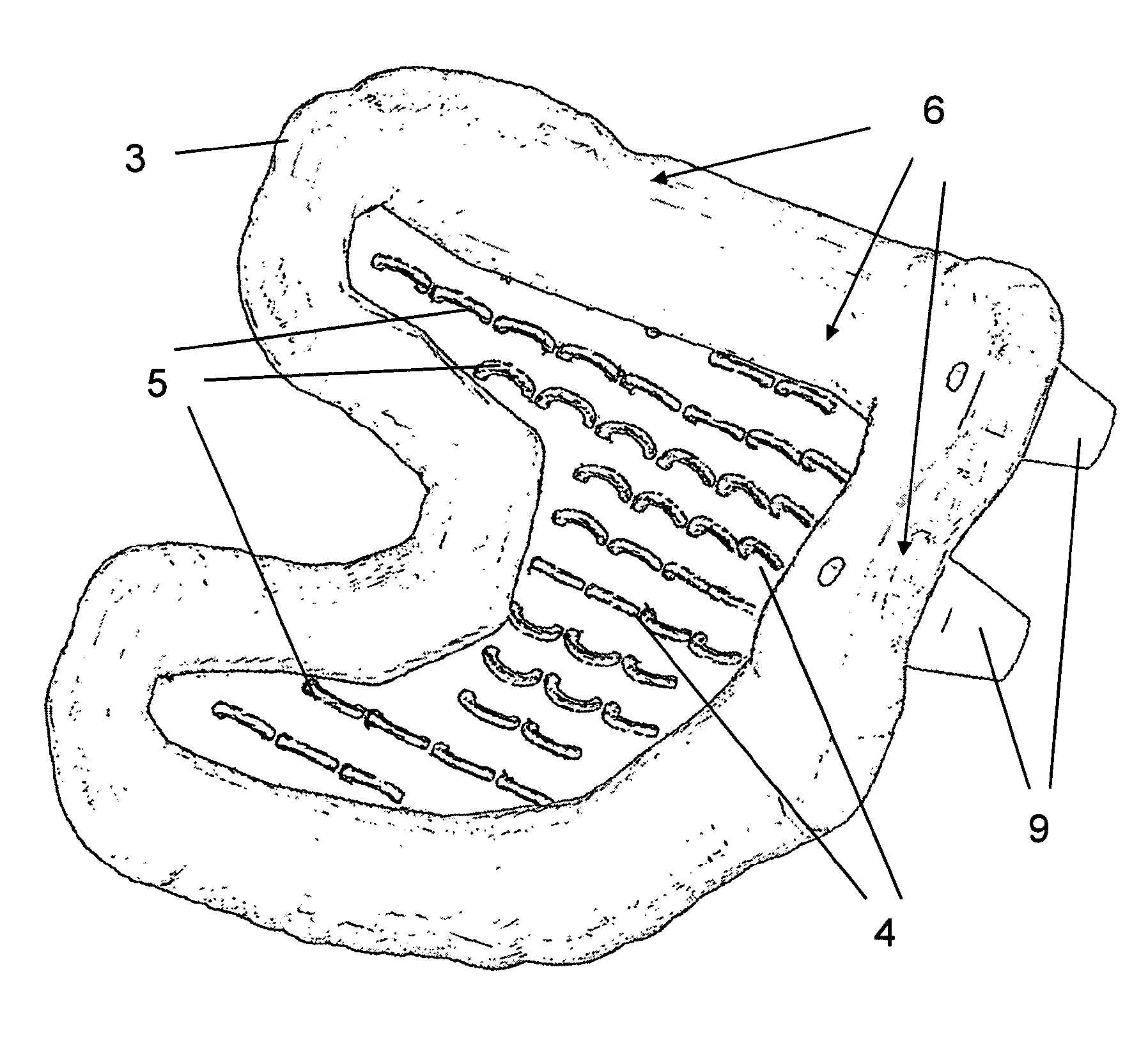
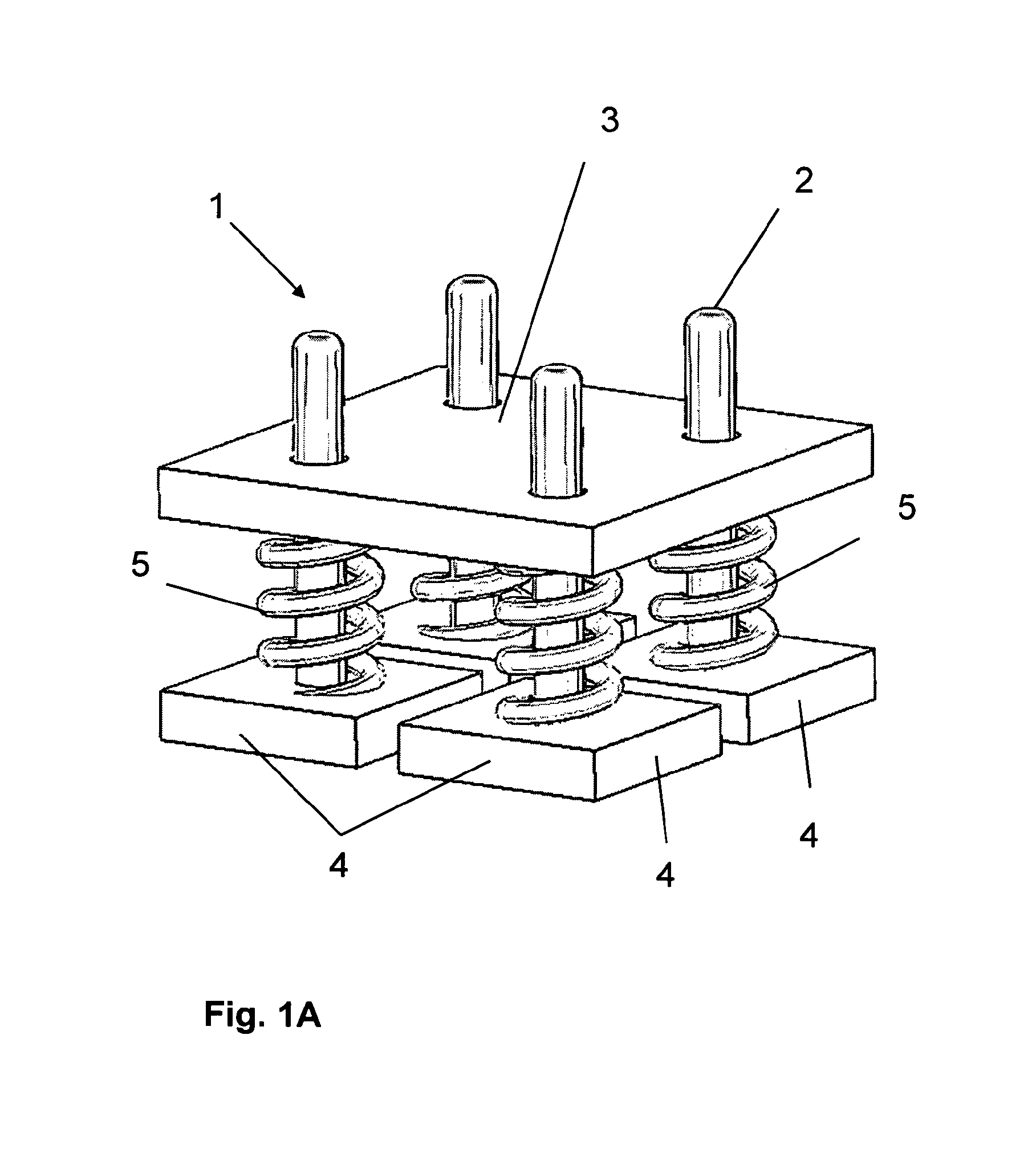
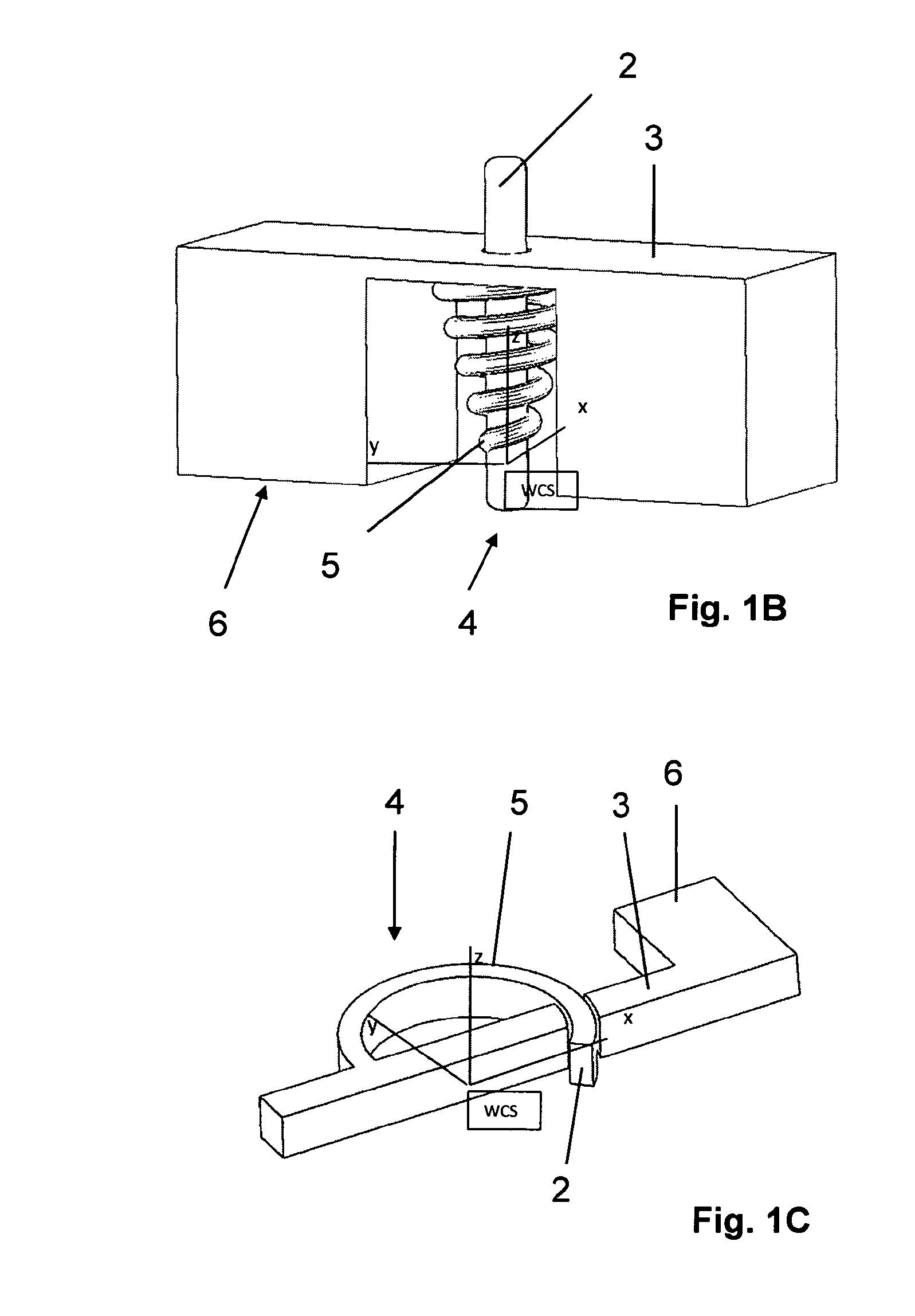
[0053]FIG. 1A is a schematic view of a feedback device for use in a surgical guide 1 according to the present invention. For a better understanding of the general working principle, the elements of the inventive guide are shown in a very simplified schematic manner.

[0054]An adaptable surgical guide 1 for an intra-operative adjustment of a contact element to a pre-planned position comprises the feedback device that has a first reference element 3 shown as a plate structure. The feedback device is shown to be a cut plane defined by the surfaces of the individual members attached to the contact elements 4. Four contact elements 4 are connected to the reference plate 3 via individual elastic elements 5 provided between the reference elemen...


PUM

PropertyMeasurementUnit
specific areaaaaaaaaaaa
areaaaaaaaaaaa
elasticaaaaaaaaaa

Abstract

The present invention relates to an adaptable therapeutic, diagnostic or surgical guide for an intra-operative adjustment of a guidance element to a pre-planned position. An advantage and innovation of the present invention is that it provides a template or guide that adapts in a controlled way to a changed intra-operative anatomical situation compared to the default planned situation. This adaption maybe purely positional but it may also include force feedback. Feedback, either visual feedback or force feedback that results in an adjustment of a guidance element is also an aspect of the present invention. For example, the feedback can contain information either about the fit of the guide or template onto a bone (in case the guide or template fits onto one bone) or about the relative position of two bones of bone fragments (e.g. ligament tension between the femur and tibia).

Description

Cross-Reference to Related Applications[0001]This application is the U.S. national stage of International Patent Application No. PCT / EP2010 / 063330, filed Sep. 10, 2010, which claims the benefit of United Kingdom Patent Application No. 0915947.6, filed Sep. 11, 2009 and U.S. Patent Application No. 61 / 242,952, filed Sep 16, 2009.TECHNICAL FIELD OF THE INVENTION[0002]The present invention relates to a medical, e.g. therapeutic, diagnostic or surgical guide for invasive medical treatments. It applies more particularly, but not exclusively, to a medical or surgical guide for computer aided and computer planned treatments in cases where the guide has to be adapted intra-operatively to a targeted area of a patient.BACKGROUND OF THE INVENTION[0003]At present, there exists an increasing number of surgical interventions that benefit from the use of medical image based patient specific surgical guides as described for example in patent applications US 2005 / 0203528 A1 and EP 1 486 900 A1.[0004]...

Claims


Application Information

Patent Timeline
Patent Type & Authority Patents(United States)
IPC IPC(8): A61B17/00B23C3/00
CPCA61B17/154A61B17/17A61B17/1764A61B2017/00862A61B2017/568Y10T409/30084B33Y80/00
Inventor GEEBELEN, BENWIRIX-SPEETJENS, ROELKEPPLER, LOUIS JAMESVANCRAEN, WILFRIED
Owner MATERIALISE NV
Learn More