
Evaluation device and method for providing a transceiver system with performance information thereof

a transceiver and performance information technology, applied in the direction of pulse technique, transmission monitoring, receiver monitoring, etc., can solve the problems of inability to use the general method of estimating the ber or the ser, and the bit error rate or the symbol error rate, which is computed according to the rayleigh fading model, is not accurate, and the method proposed by b. y. wang and w. x. zheng cannot be used for estimating the ber or

Inactive Publication Date: 2014-04-22
I-SHOU UNIVERSITY
View PDF3 Cites 2 Cited by
  • Summary
  • Abstract
  • Description
  • Claims
  • Application Information

AI Technical Summary

Benefits of technology

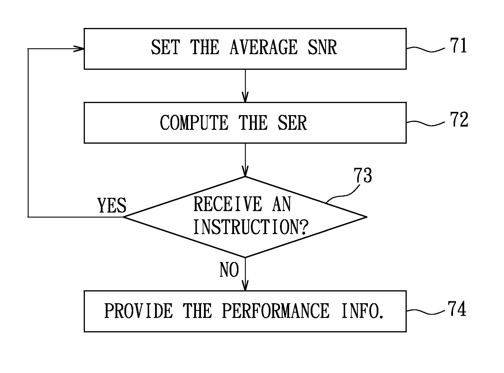
The present invention provides an evaluation device and method for a transceiver system that can provide performance information with relatively less computation. The evaluation device sets an average signal-to-noise ratio (SNR) for the channel between the transmitter and the receiver of the transceiver system and estimates a symbol error rate related to the signal received by the receiver based on the fading parameter and the average SNR. The evaluation device then provides the transceiver system with the average SNR and the symbol error rate as the performance information of the transceiver system. This allows for better performance evaluation and optimization of the transceiver system.

Problems solved by technology

However, Rayleigh fading model is only suitable for simulation of the fading simply attributed to multipath propagation, and is inappropriate for simulation of masking, fading, or other interferences in a metropolis.
Therefore, a bit error rate (BER) or a symbol error rate (SER), which is computed according to Rayleigh fading model, is not accurate.
Therefore, the method proposed by B. Y. Wang and W. X. Zheng for estimating the BER or the SER cannot be used generally when the power of M-PSK or M-QAM is not equal to 2.

Method used


Image

  • Evaluation device and method for providing a transceiver system with performance information thereof
  • Evaluation device and method for providing a transceiver system with performance information thereof
  • Evaluation device and method for providing a transceiver system with performance information thereof

Examples


Embodiment Construction

[0024]Referring to FIG. 4, a transceiver system 100 under a transmit antenna selection / maximal-ratio combining (TAS / MRC) scheme includes a transmitter 1 and a receiver 2 coupled to the preferred embodiment of an evaluation device 300 of this invention. The transmitter 1 includes a diversity unit 11 and a number LT (LT>1) of transmit antennas 12, and the receiver 2 includes a number LR (LR>1) of receive antennas 22, a synthesis unit 21, and a channel estimator 23. For illustrative purpose, in FIG. 4, the transmitter 1 includes three (LT=3) of the transmit antennas 12, and the receiver 2 includes two (LR=2) of the receive antennas 22.

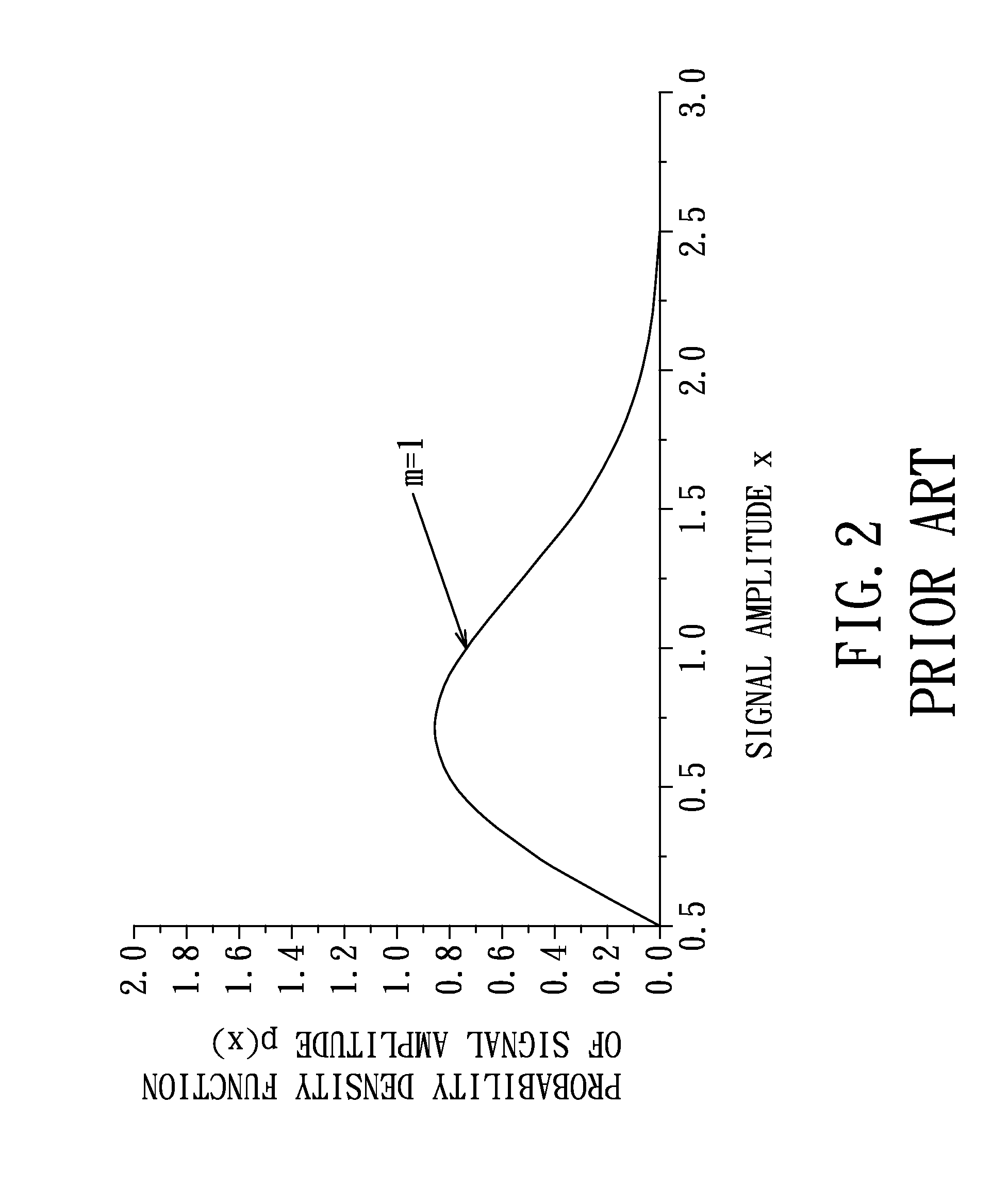
[0025]In such a TAS / MRC scheme, there are a number LT×LR of possible channels, each of which is defined by one of the transmit antennas 12 and one of the receive antennas 22 and can be simulated using Nakagami channel model (see Nakagami distribution shown in FIG. 3) with a positive fading parameter (m). The channel estimator of the receiver 2 is operable...


PUM


Abstract

An evaluation device is configured to provide a transceiver system with performance information thereof. The transceiver system models a channel between a transmitter and a receiver thereof using Nakagami distribution with a fading parameter. The evaluation device includes a setting module operable to set an average signal-to-noise rate (SNR) for the channel between the transmitter and the receiver, a computing module operable to estimate a symbol error rate related to a signal received by the receiver from the transmitter based upon the fading parameter and the average SNR, and an output module operable to provide the average SNR and the symbol error rate as the performance information of the transceiver system.

Description

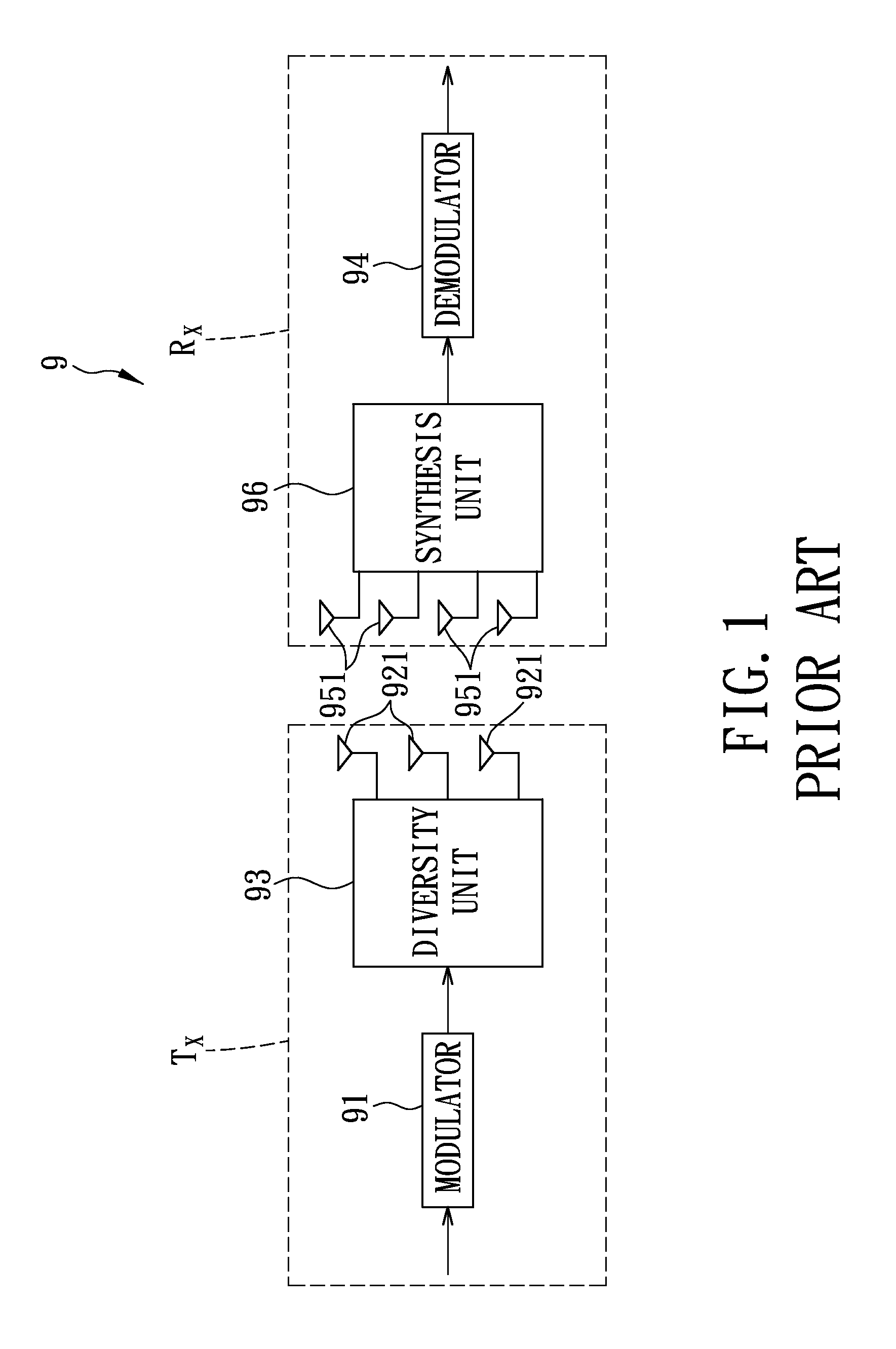
BACKGROUND OF THE INVENTION[0001]1. Field of the Invention[0002]The present invention relates to an evaluation device and method for providing a transceiver system with performance information thereof, more particularly to an evaluation device and method for providing a transceiver system, which models a channel thereof using Nakagami distribution, with performance information thereof.[0003]2. Description of the Related Art[0004]Referring to FIG. 1, a conventional transceiver system 9 under a transmit antenna selection / maximal-ratio combining (TAS / MRC) scheme includes a transmitter (TX) and a receiver (RX). The transmitter (TX) includes a modulator 91, a diversity unit 93 electrically connected to the modulator 91, and a plurality of transmit antennas 921 electrically connected to the diversity unit 93. The receiver (RX) includes a demodulator 94, a synthesis unit 96 electrically connected to the demodulator 94, and a plurality of receive antennas 951 electrically connected to the s...

Claims


Application Information

Patent Timeline
Patent Type & Authority Patents(United States)
IPC IPC(8): H04B1/38
CPCH04B17/008H04B17/0092H04B7/0413H04B17/29H04B17/3911
Inventor CHIANG, CHING-TAIWU, RONG-CHINGOUYANG, CHEN-SENTSAI, JONG-IAN
Owner I-SHOU UNIVERSITY
Learn More