Retinal prosthesis techniques

a technology of retinal prosthesis and retinal bone, applied in the field of implantable medical devices, can solve the problems of retinal malfunction, blindness, visual impairment, etc., and achieve the effect of facilitating the refraction of visible ligh

Active Publication Date: 2014-04-22
NANO RETINA INC
View PDF310 Cites 16 Cited by
  • Summary
  • Abstract
  • Description
  • Claims
  • Application Information

AI Technical Summary

Benefits of technology

[0013]The intraocular device typically comprises a support substrate and an array of electrodes protruding from the support substrate. (In this context, in the specification and in the claims, “array” is meant to include rectangular as well as non-rectangular arrays (such as circular arrays). The protruding electrodes are shaped to define electrically-exposed tips which penetrate retinal tissue of the subject, bringing the electrodes in contact with the tissue. For some applications, a surface of the electrodes is treated to increase roughness and surface area of the electrodes, thus reducing electrode impendence and facilitating retinal stimulation and / or axon regeneration. Additionally or alternatively, the exposed tips of the electrodes have perforations passing therethrough, further increasing the surface area of the electrodes and allowing neuronal processes, to pass through and intertwine with the electrodes.
[0016]The inventors have identified that, for some applications, sufficient stimulation of retinal tissue is a characteristic for consideration in enabling proper function of a retinal prosthesis. In particular, facilitating stimulation of the bipolar cell layer of the retina, which in turn stimulates ganglion cells, is a characteristic for consideration in retinal prosthesis provided by some applications of the present invention. The ganglion cells, whose axons form the optic nerve, further transmit the visual information to the brain resulting in the formation of an image. Penetrating perforated electrodes, in contrast to surface electrodes known in the art which sit on the surface of tissue, are configured to extend from either an epi-retinal or a sub-retinal implantation site and penetrate retinal tissue to directly contact and drive electrical charge into the bipolar cell layer from typically less than 10 um from the nearest bipolar cell. Rough electrode surfaces and perforations passing through the electrodes allow neuronal processes to grow therethrough, further improving cell-electrode coupling and increasing stimulation. Increased and direct contact of the retinal tissue by penetrating perforated electrodes enhances stimulation of the retina resulting in enhanced image resolution.
[0101]In some applications, the intraocular device includes a plurality of microlenses coupled to the energy receiver, facilitating refraction of visible light toward the photosensors.
[0115]In some applications, the mount includes a filter configured to prevent transmission to the photosensors of ambient non-visible light.

Problems solved by technology

Retinal malfunction, due to degenerative retinal diseases, is a leading cause of blindness and visual impairment.

Method used


Image

  • Retinal prosthesis techniques
  • Retinal prosthesis techniques
  • Retinal prosthesis techniques

Examples


Embodiment Construction

[0008]Some applications of the invention relate generally to implantable medical devices and more specifically to a retinal prosthesis.

BACKGROUND

[0009]Retinal malfunction, due to degenerative retinal diseases, is a leading cause of blindness and visual impairment. Implantation of a retinal prosthesis is a technology for restoring some useful vision in individuals suffering from retinal-related blindness.

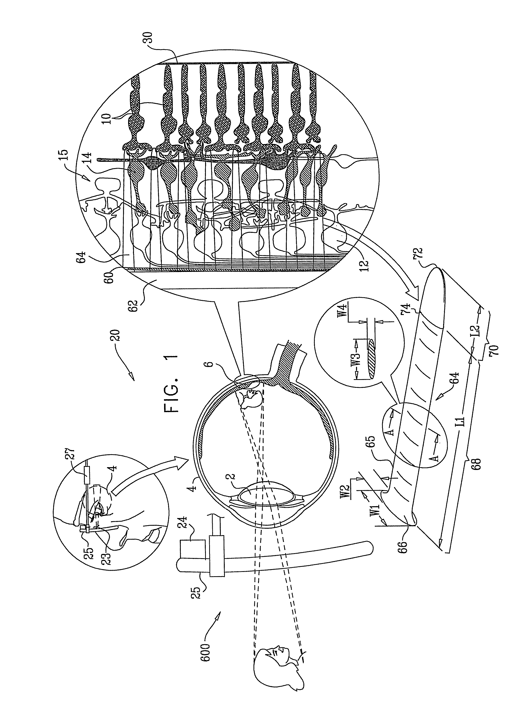
[0010]The retina is a multi-layered light-sensitive structure that lines the posterior, inner part of the eye. The retina contains photoreceptor cells, for example rods and cones, which capture light and convert light signals into neural signals transmitted through the optic nerve to the brain. Rods are responsible for light sensitive, low resolution black and white vision, whereas cones are responsible for high resolution color vision. Most cones lie in the fovea, which defines the center of the retina. A bipolar cell layer exists between the photoreceptors and ganglion cells of the...


PUM


Abstract

Apparatus for use with an external non-visible light source is provided. The apparatus comprises an intraocular device configured for implantation in a human eye, and comprising an energy receiver. The energy receiver is configured to receive light emitted from the external non-visible light source, and extract energy from the emitted light for powering the intraocular device. The intraocular device is configured to regulate a parameter of operation of the intraocular device based on a modulation of the light emitted by the external non-visible light source and received by the energy receiver. Other embodiments are also described.

Description

CROSS-REFERENCES TO RELATED APPLICATIONS[0001]The present application is a continuation-in-part of:[0002](a) U.S. Ser. No. 13 / 103,264 (US 2012 / 0035726) to Gross et al.,[0003](b) U.S. Ser. No. 12 / 852,218 (US 2012 / 0035725) to Gefen et al., which issued as U.S. Pat. No. 8,428,740.[0004](c) U.S. Ser. No. 12 / 687,509 (US 2011 / 0172736) to Gefen et al.,[0005](d) U.S. Ser. No. 13 / 148,461 (US 2012 / 0041514) to Gross et al., which is the US national stage of PCT / IL2010 / 000097 (WO 2010 / 089739), and[0006](e) U.S. Ser. No. 12 / 368,150 (US 2010 / 0204754) to Gross et al.[0007]All of the above-referenced applications are incorporated herein by reference.FIELD OF EMBODIMENTS OF THE INVENTION[0008]Some applications of the invention relate generally to implantable medical devices and more specifically to a retinal prosthesis.BACKGROUND[0009]Retinal malfunction, due to degenerative retinal diseases, is a leading cause of blindness and visual impairment. Implantation of a retinal prosthesis is a technology ...

Claims


Application Information

Patent Timeline
Patent Type & Authority Patents(United States)
IPC IPC(8): A61N1/05
CPCA61F2/1659A61F2/14A61F2/1624A61N1/0543A61N1/36046A61N1/3787A61N1/37217A61F2/148A61F9/00A61F9/008
Inventor GEFEN, RA'ANANGROSS, YOSSILIRAN, TUVIAVAINGAST, SHAI
Owner NANO RETINA INC
Why Eureka
Try Eureka