
Flat panel display device and method of fabricating the same

a technology of display panel and display panel, which is applied in the direction of casing/cabinet/drawer, casing/cabinet/drawer details of electrical appliances, instruments, etc., can solve the problem of image display on display panel may be distorted, and achieve the effect of reducing the empty space between

Active Publication Date: 2014-04-29
SAMSUNG DISPLAY CO LTD
View PDF73 Cites 2 Cited by
  • Summary
  • Abstract
  • Description
  • Claims
  • Application Information

AI Technical Summary

Benefits of technology

The present invention provides a flat panel display device with a more closely attached display panel and protection board, reducing empty space between them. Additionally, a bezel is included to prevent damage to the display panel from external impact. The image is displayed on the display panel, while the protection board is placed on top. The bezel surrounds the sides and bottom of the display panel.

Problems solved by technology

Thus, the display panel and the protection board are not sufficiently attached, and thus the image displayed on the display panel may be distorted due to an empty space between the display panel and the protection board and a difference in refractive index between an upper substrate of the display panel and the protection board.
Alternatively, when a black matrix and a protection board are disposed on a display panel, a surface step difference of the display panel or the protection board caused by the black matrix results in bubbles made when the adhesion of the display panel to the protection board, and thus an upper substrate of the display panel and the protection board may not be closely attached.

Method used


Image

  • Flat panel display device and method of fabricating the same
  • Flat panel display device and method of fabricating the same
  • Flat panel display device and method of fabricating the same

Examples


Embodiment Construction

[0022]Reference will now be made in detail to the present examples of the present invention, examples of which are illustrated in the accompanying drawings. In the drawings, lengths and thicknesses of layers and regions may be exaggerated for convenience, and like numerals denote the like elements throughout the specifications.

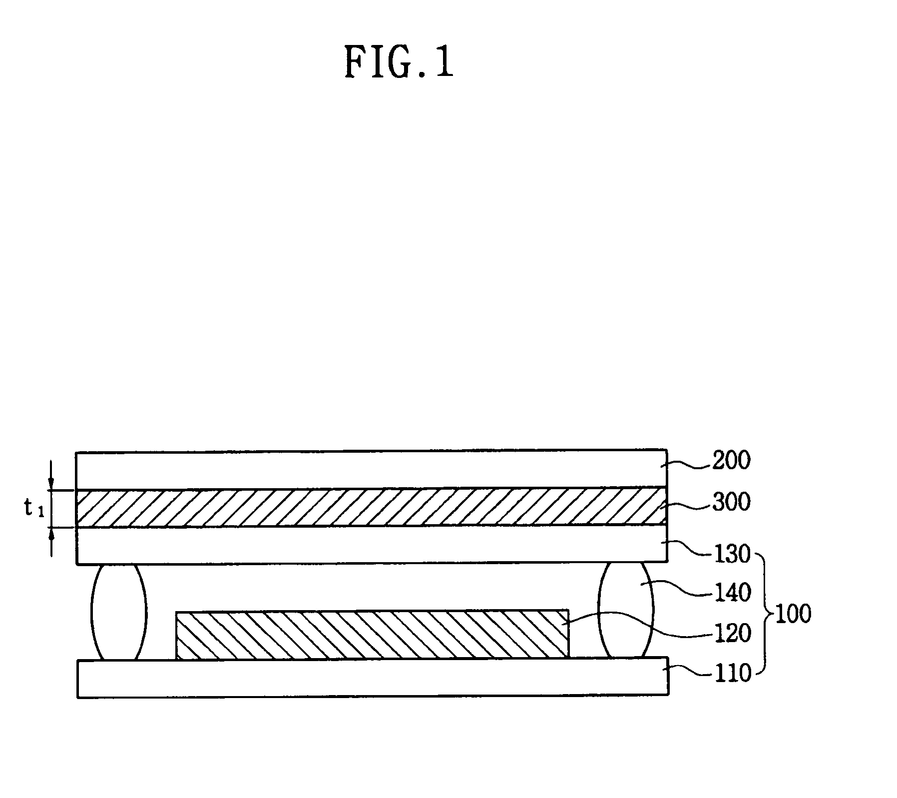
[0023]FIG. 1 is a cross-sectional view of a flat panel display device according to a first example embodiment of the present invention.

[0024]Referring to FIG. 1, the flat panel display device according to a first example embodiment of the present invention includes a display panel 100 having a lower substrate 110, an upper substrate 130 and at least one light emitting element 120 disposed between the lower substrate 110 and the upper substrate 130, a protection board 200 disposed on the display panel 100, and an adhesive layer 300 disposed between the display panel 100 and the protection board 200 and having a first thickness t1. Specifically, the adhesive lay...


PUM

PropertyMeasurementUnit
refractive indexaaaaaaaaaa
pressureaaaaaaaaaa
thickness t1aaaaaaaaaa

Abstract

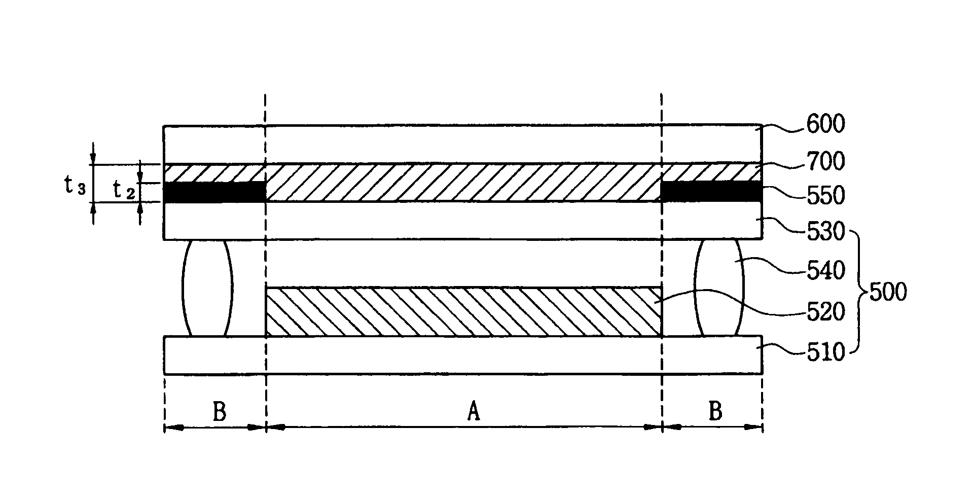
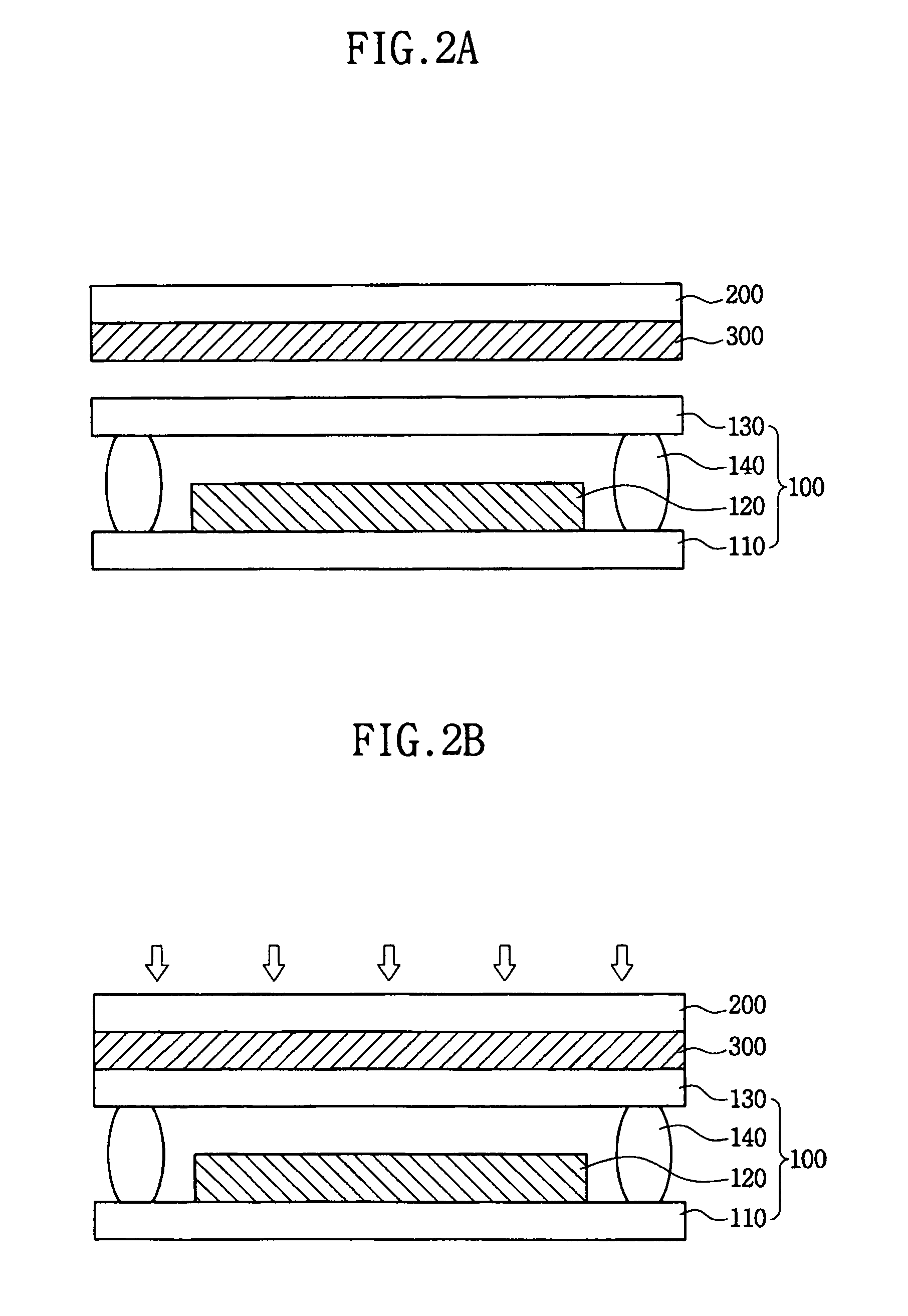
Provided are a flat panel display device including a protection board configured to prevent damage of a display panel from external impact, and a method of fabricating the same. The display panel and the protection board are closely attached, and distortion of an image displayed on the display panel due to a space between the display panel and the protection board can be prevented. The flat panel display device includes a display panel including a lower substrate, an upper substrate and at least one light emitting element disposed between the lower and upper substrates, a protection board disposed on the display panel, and an adhesive layer disposed between the display panel and the protection board. The method includes preparing a display panel including a lower substrate, an upper substrate and at least one light emitting element disposed between the lower and upper substrates, preparing a protection board, forming an adhesive layer on one surface of the display panel or the protection board, arranging the display panel and the protection board such that the adhesive layer is disposed between the display panel and the protection board, and applying a predetermined pressure to attach the display panel to the protection board.

Description

CLAIM OF PRIORITY[0001]This application makes reference to, incorporates the same herein, and claims all benefits accruing under 35 U.S.C. §119 from applications earlier filed in the Korean Intellectual Property Office on 28 Oct. 2008 and there duly assigned Serial No. 10-2008-0105943, and on 28 Oct. 2008 and there duly assigned Serial No. 10-2008-0105944.BACKGROUND OF THE INVENTION[0002]1. Field of the Invention[0003]The present invention relates to a flat panel display device including a protection board to prevent damage of a display panel from external impact, and more particularly, to a flat panel display device, in which a display panel and a protection board are closely attached, and a space between the display panel and the protection board results in preventing distortion of an image displayed on the display panel, and a method of fabricating the same.[0004]2. Description of the Related Art[0005]Flat panel display devices are used as substitutes for cathode-ray tube display...

Claims


Application Information

Patent Timeline
Patent Type & Authority Patents(United States)
IPC IPC(8): G02F1/1333
CPCH05K5/02H01L51/5275H01L51/5237Y10T428/24777H10K59/879H10K59/8722H10K50/841H10K50/858
Inventor KWAK, NOH-MINCHO, DAI-HANYOO, GI-NAKIM, MIN-JAELEE, JEONG-NOJUNG, WOO-SUKLEE, DUK-JIN
Owner SAMSUNG DISPLAY CO LTD
Learn More