
Multiple input multiple output transceiver

a transceiver and input multiple technology, applied in the field of multi-input multiple output (mimo) transceivers, can solve the problems of longer-range applications of wireless devices, wireless device antennas still have a certain transmission distance limit,

Active Publication Date: 2014-04-29
CLOUD NETWORK TECH SINGAPORE PTE LTD
View PDF14 Cites 8 Cited by
  • Summary
  • Abstract
  • Description
  • Claims
  • Application Information

AI Technical Summary

Problems solved by technology

However, antennas of wireless devices still have a certain transmission distance limit, which may prevent longer-range applications for the wireless device.

Method used


Image

  • Multiple input multiple output transceiver
  • Multiple input multiple output transceiver
  • Multiple input multiple output transceiver

Examples


Embodiment Construction

[0008]The disclosure is illustrated by way of example and not by way of limitation in the figures of the accompanying drawings, in which like references indicate similar elements. It should be noted that references to “an” or “one” embodiment in this disclosure are not necessarily to the same embodiment, and such references can mean “at least one.”

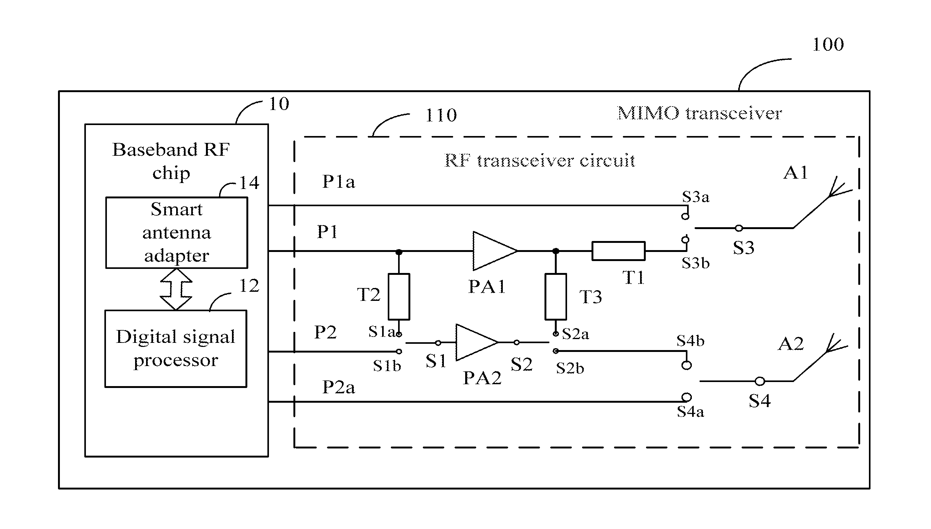
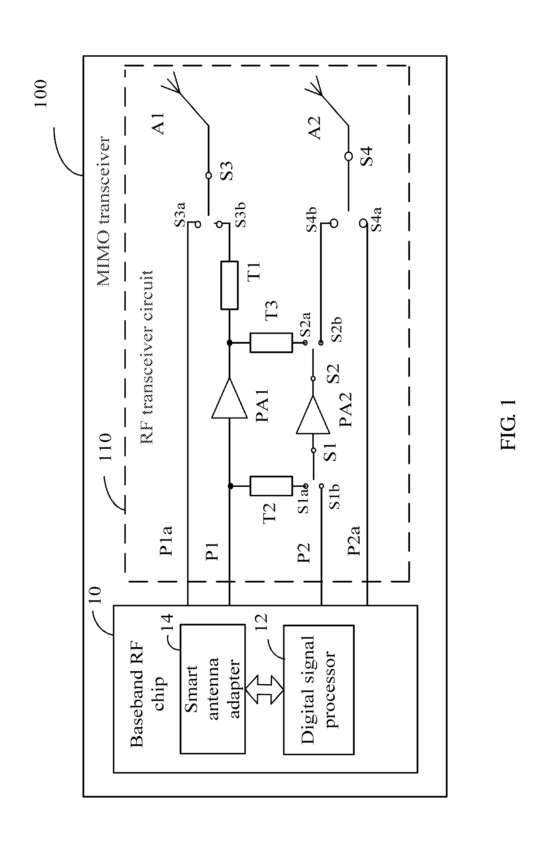
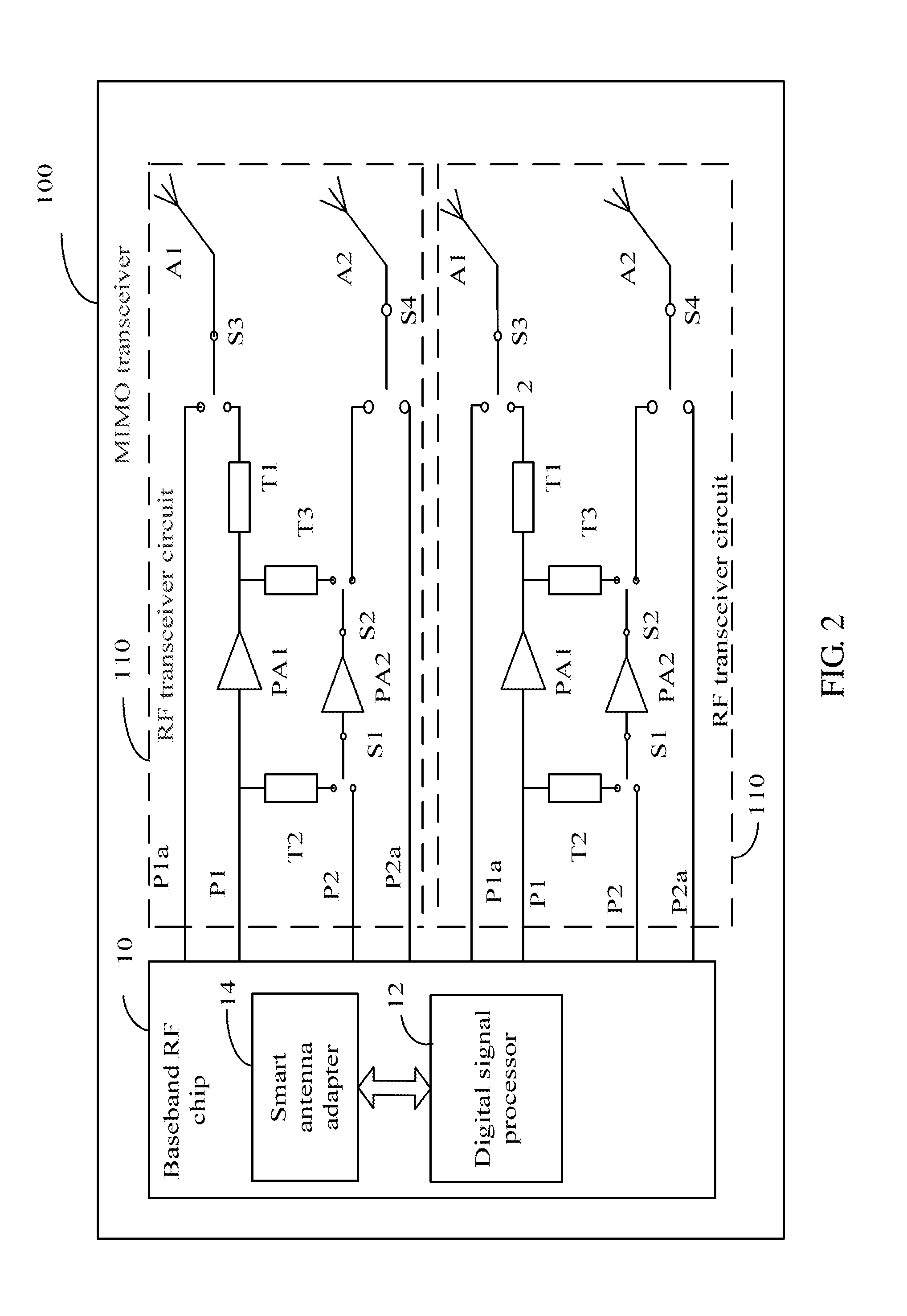
[0009]FIG. 1 is a circuit diagram of one embodiment of a multiple input multiple output (MIMO) transceiver 100. In one embodiment, the MIMO transceiver 100 comprises a baseband radio frequency (RF) chip 10 and an RF transceiver circuit 110. The RE transceiver circuit 110 comprises a first antenna A1, a second antenna A2, a first receiving channel P1a, a second receiving channel P2a, first transmitting channel P1, a second transmitting channel P2, a first single pole double throw (SPDT) switch S1, and a second SPDT switch S2.

[0010]The first antenna A1 and the second antenna A2 receive and transmit RF signals. The baseband RF chip 10 is conn...


PUM


Abstract

An exemplary MIMO transceiver includes a first transmitting channel and a second transmitting channel. The first transmitting channel includes a first power amplifier and a first transmission line which are connected together in series. The second transmitting channel includes a second power amplifier. A common terminal of a first single pole double throw (SPDT) switch is connected to the second power amplifier. A first terminal of the first SPDT switch is connected to the first power amplifier through a second transmission line. A common terminal of a second SPDT switch is connected to the second power amplifier. A first terminal of second SPDT switch is connected to the first power amplifier through a third transmission line. A second terminal of the second SPDT switch is connected to a second antenna. The first power amplifier, the second transmission line, and the third transmission line cooperatively act as a balance power amplifier.

Description

BACKGROUND[0001]1. Technical Field[0002]The disclosure relates to multiple input multiple output (MIMO) transceivers.[0003]2. Description of Related Art[0004]Wireless devices are popular nowadays. A transmission distance of radio frequency (RF) signals transmitted by wireless devices is very important. The gain of a wireless device may be increased by changing the shape of an antenna of the wireless device, so as to increase the transmission distance of RF signals transmitted by the antenna. However, antennas of wireless devices still have a certain transmission distance limit, which may prevent longer-range applications for the wireless device.BRIEF DESCRIPTION OF THE DRAWINGS[0005]Many aspects of the present embodiments can be better understood with reference to the following drawings. The components in the drawings are not necessarily drawn to scale, the emphasis instead being placed upon clearly illustrating the principles of the present embodiments. Moreover, in the drawings, a...

Claims


Application Information

Patent Timeline
Patent Type & Authority Patents(United States)
IPC IPC(8): H04B7/02H04L1/02
CPCH04B7/0413H04B1/04H04B1/40
Inventor HUNG, LIANG-HSIEN
Owner CLOUD NETWORK TECH SINGAPORE PTE LTD
Learn More