Autobrake and decel control built-in test equipment

a technology of autobrake and deceleration control, applied in the field of brakes, can solve the problems of difficult real-world testing of the autobrake system, difficult to obtain data while the vehicle is undergoing maintenance,

Active Publication Date: 2014-04-29
THE BF GOODRICH CO
View PDF12 Cites 11 Cited by
  • Summary
  • Abstract
  • Description
  • Claims
  • Application Information

AI Technical Summary

Benefits of technology

[0007]The BITE also may include logic that responds to certain events (e.g., the logic may simulate an actual touchdown of an aircraft based on the state of various sensors). For example, if, during test mode, the WOW sensor is reporting that weight is not on the wheels, then the signal generator may output data corresponding to zero wheel speed. Upon the WOW sensor reporting that weight is on wheels, the signal generator may automatically output a signal corresponding to high wheel speed, and then decrease the signal so as to approximate deceleration of the vehicle (e.g., typical touchdown speed of an aircraft). This simulates the landing process of an aircraft, and can be used to monitor and evaluate events and conditions of the autobrake system, thereby providing the technician with accurate view of how the system will operate in normal use.

Problems solved by technology

However, since autobrake control utilizes vehicle speed data to implement the respective control routines, such data is difficult to obtain while the vehicle is undergoing maintenance (e.g., while in a hanger or maintenance bay).
Thus, performing real-world tests on the autobrake system can be difficult.

Method used


Image

  • Autobrake and decel control built-in test equipment
  • Autobrake and decel control built-in test equipment
  • Autobrake and decel control built-in test equipment

Examples


Embodiment Construction

[0021]The principles of the invention will now be described with reference to the drawings. Because the invention was conceived and developed for use in an aircraft braking system, it will be herein described chiefly in this context. However, the principles of the invention in their broader aspects can be adapted to other types of autobraking systems.

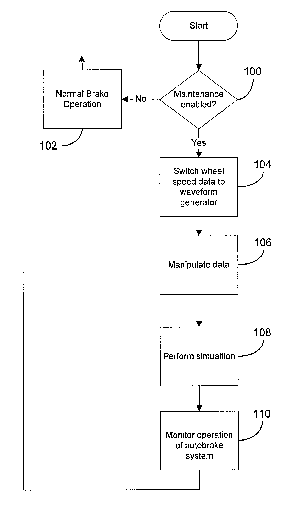
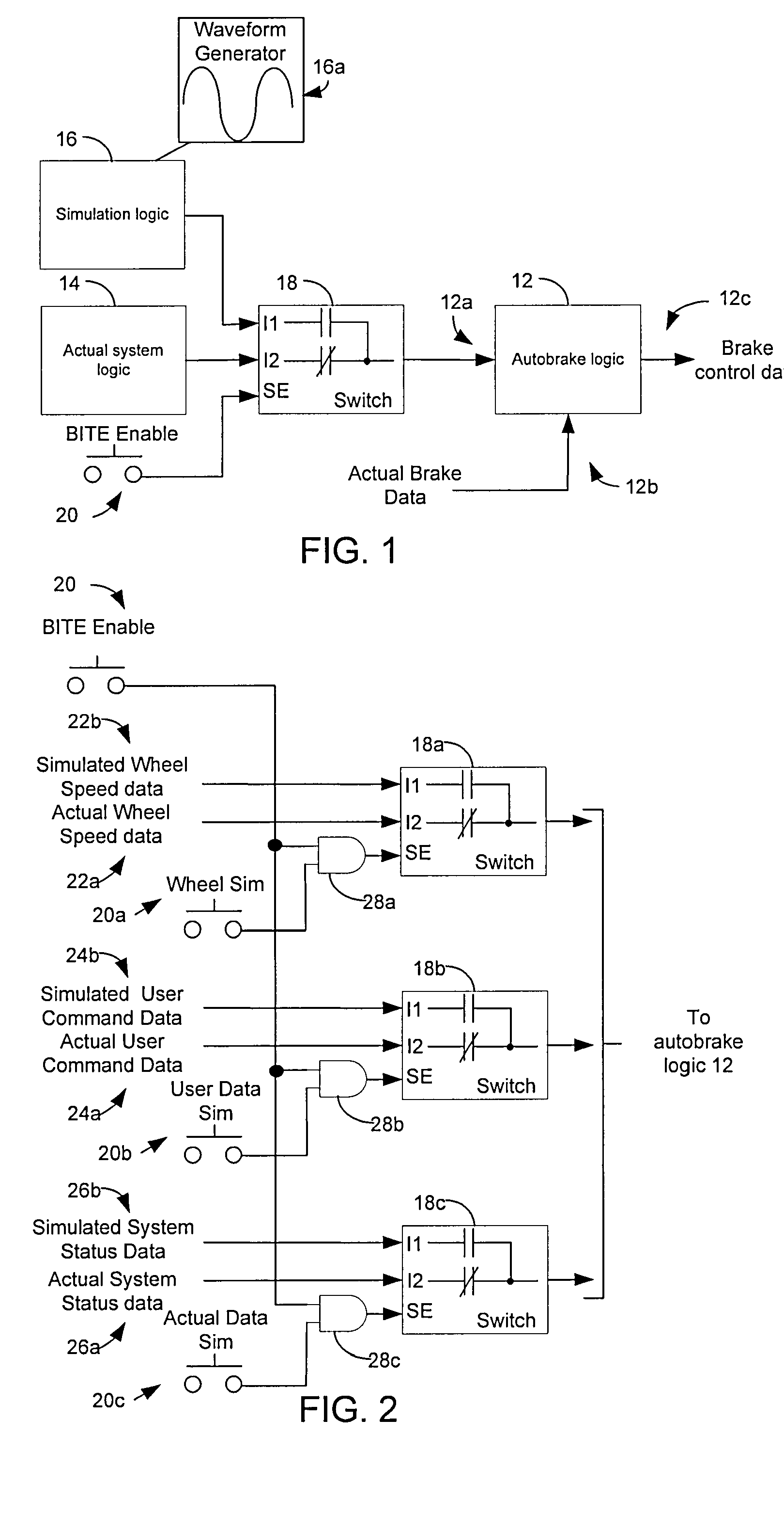
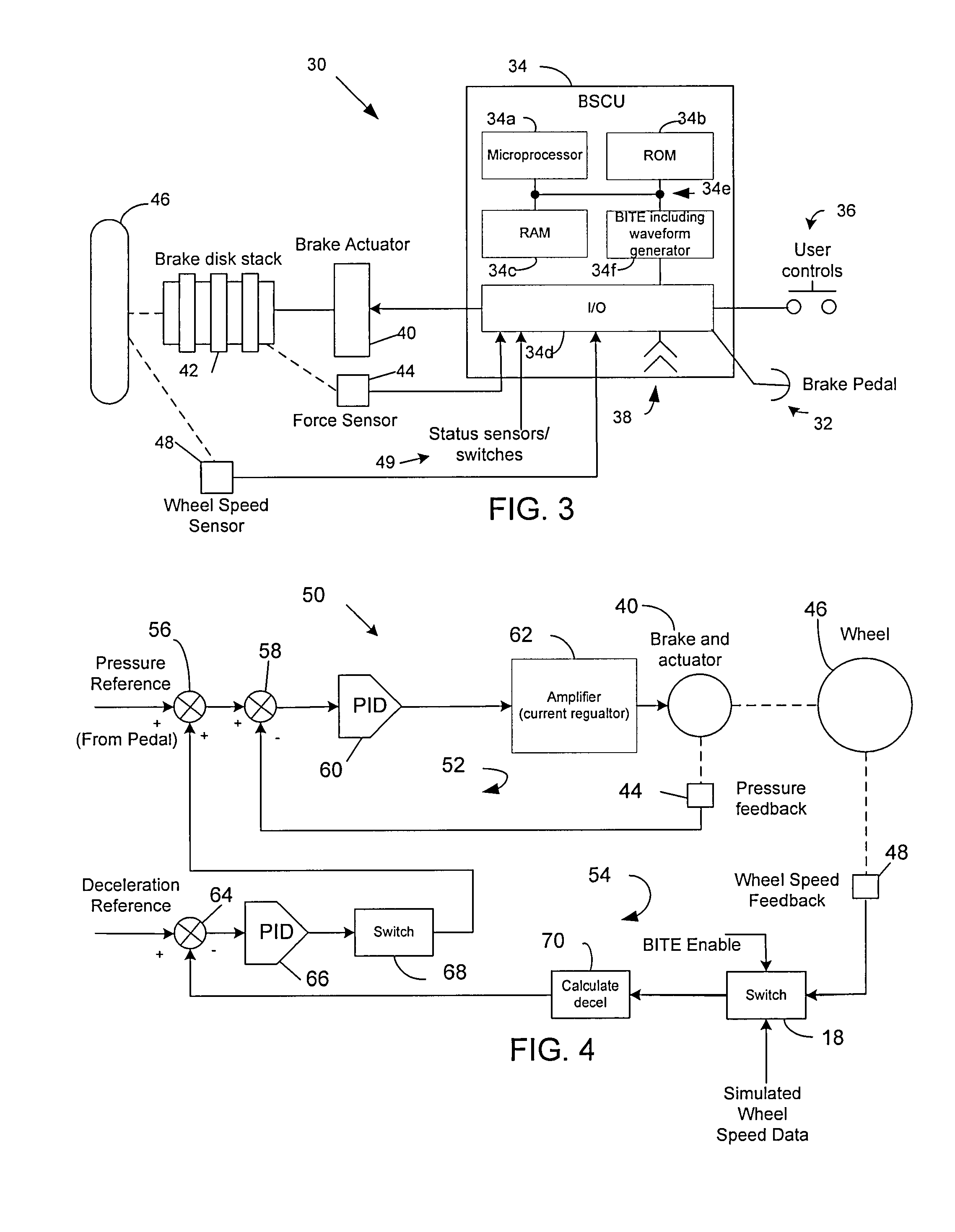
[0022]The present invention provides a system, apparatus and method that allow maintenance personnel to quickly and easily test operation of a vehicle's brake system. More particularly, a means for generating a simulated wheel speed signal and for switching the simulated wheel speed signal in place of data from wheel speed sensors is provided. This enables a maintenance technician to exercise the autobrake system functions without having to monitor the system during an actual landing. Not only does this significantly simplify maintenance operations for the technician, but it also minimizes costs as the aircraft does not need to perform ...


PUM


Abstract

A system, apparatus and method provide a means for testing operation of a vehicle brake system. More particularly, a brake controller for controlling operation of the brake system includes a signal generator that can generate data indicative of wheel speed. Based on a user command, the controller uses either actual wheel speed data or simulated wheel speed data as inputs for controlling brake operation. The controller also includes logic for exercising various braking functions so as to enable maintenance personal to determine operational systems of the brake system.

Description

FIELD OF THE INVENTION[0001]The present invention relates generally to brakes and, more particularly, to a method, apparatus, and system for controlling brakes of a vehicle.BACKGROUND[0002]Autobrake brake control systems have been in widespread use for many years. Such systems enable a vehicle, such as an aircraft, to be quickly and safely brought to a stop. More particularly, autobrake functionality allows a pilot to select from several automatic deceleration levels for landing, or to arm a rejected take off (RTO) setting prior to takeoff. During autobraking, pressure is automatically applied to the brakes independent of the pilot's brake pedals. In multiwheel vehicles, the same pressure is usually applied to all the wheels. The system regulates brake pressure to compensate for various effects, such as aircraft drag, thrust reversers, and spoilers, to maintain the selected deceleration level. A typical autobrake system has at least three levels of deceleration: low, medium, and max...

Claims


Application Information

Patent Timeline
Patent Type & Authority Patents(United States)
IPC IPC(8): G01M17/00G06F19/00G06F11/30G06F7/00G07C5/00
CPCB60T2270/406B60T17/221B60T8/1703B60T8/885B64C25/426B60T7/12B60T17/22
Inventor CAHILL, ERIC D.METZGER, JR., RICHARD P.
Owner THE BF GOODRICH CO
Why Eureka
Try Eureka