
Organic electroluminescent device

a technology of electroluminescent devices and organs, which is applied in the direction of instruments, discharge tubes, luminescent devices, etc., can solve the problems of reducing the aperture ratio of the oeld, and the limitation of the area of the dead zon

Active Publication Date: 2014-05-06
LG DISPLAY CO LTD
View PDF20 Cites 18 Cited by
  • Summary
  • Abstract
  • Description
  • Claims
  • Application Information

AI Technical Summary

Benefits of technology

The patent is about an organic electroluminescent device (OELD) that has improved visibility, color reproduction, and resolution. The technical effect is to provide an OELD with better optical performance.

Problems solved by technology

However, there is a technical limitation to reducing the area of the dead zones.
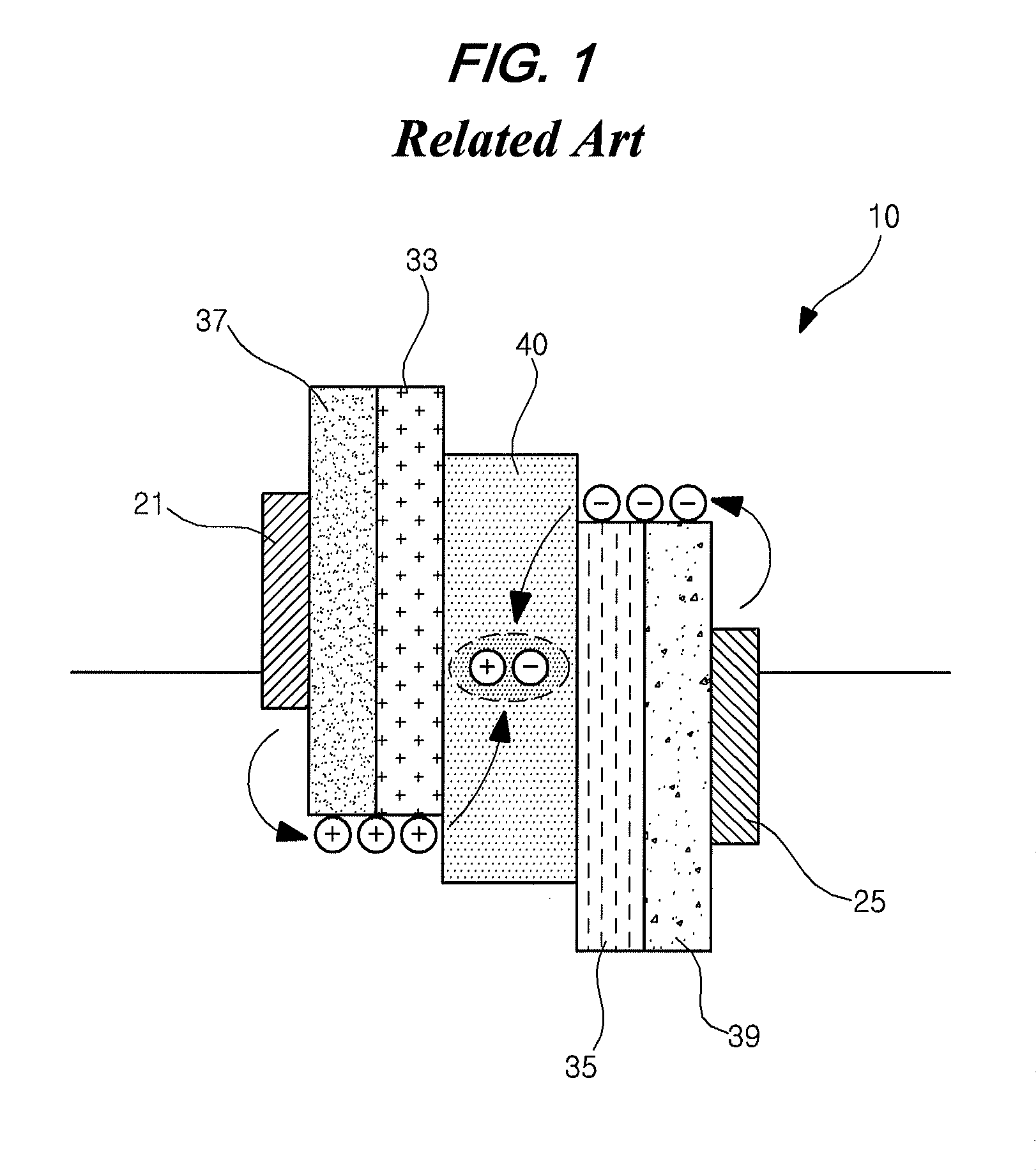
Unfortunately, by reducing the area of the emission material layer, the aperture ratio of the OELD is reduced.

Method used


Image

  • Organic electroluminescent device
  • Organic electroluminescent device
  • Organic electroluminescent device

Examples


Embodiment Construction

[0025]Reference will now be made in detail to the exemplary embodiments, which are illustrated in the accompanying drawings.

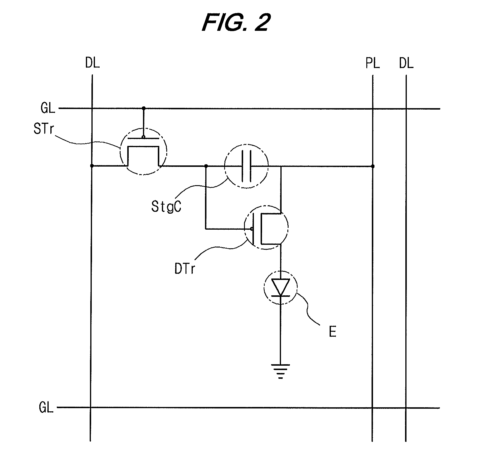
[0026]FIG. 2 is a circuit diagram showing an OELD according to an embodiment of the present invention. As shown in FIG. 2, an OELD includes a gate line “GL”, a data line “DL”, a power supply line “PL”, a switching thin film transistor (TFT) “STr”, a storage capacitor “StgC”, a driving TFT “DTr”, and an organic electroluminescent diode “E”. The gate line “GL” and the data line “DL” cross each other, and the power supply line “PL” is formed to be parallel to the data line “DL”. The switching TFT “STr” is formed at crossing portion of the gate and data line “GL” and “DL”. The driving TFT “DTr” is electrically connected to the switching TFT “STr”.

[0027]The driving TFT “DTr” is electrically connected to the organic electroluminescent diode “E”. In more detail, a first electrode of the organic electroluminescent diode “E” is connected to a drain electrode of the driv...


PUM


Abstract

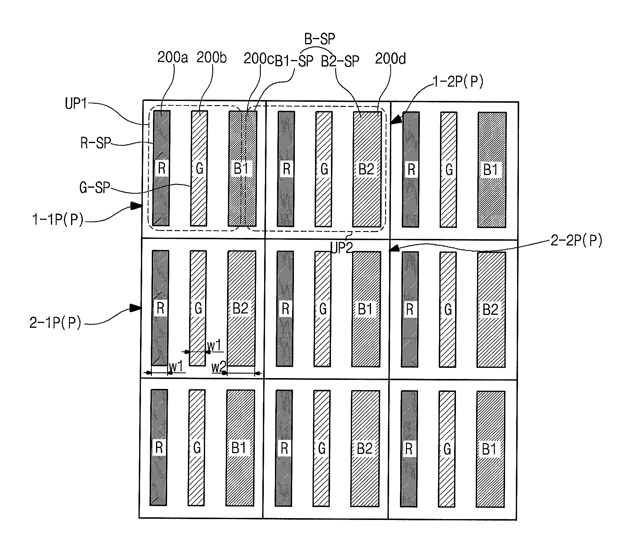
An organic electroluminescent device including a first red sub-pixel region, a first green sub-pixel region and a deep blue sub-pixel region in a first pixel region; and a second red sub-pixel region, a second green sub-pixel region and a sky blue sub-pixel region in a second pixel region adjacent to the first pixel region, wherein each of the first and second red sub-pixel regions includes a first electrode, a red organic emission material pattern and a second electrode, each of the first and second green sub-pixel regions includes the first electrode, a green organic emission material pattern and the second electrode, wherein the deep blue sub-pixel region includes the first electrode, a deep blue organic emission material pattern and the second electrode, and the sky blue sub-pixel region includes the first electrode, a sky blue organic emission material pattern and the second electrode, and wherein an unit pixel displaying an image includes at least one of the deep blue sub-pixel region and the sky blue sub-pixel region with the second red sub-pixel region and the second green sub-pixel region.

Description

[0001]The present application claims the benefit of Korean Patent Application No. 10-2010-0083631 filed in Korea on Aug. 27, 2010, which is herein incorporated by reference in its entirety.BACKGROUND[0002]1. Technical Field[0003]The present disclosure relates to an organic electroluminescent device (OELD), and more particularly, to an OELD having advantages in an aperture ratio, color reproduction and resolution.[0004]2. Related Art[0005]Cathode ray tubes have been widely used as display devices. However, recently flat panel display devices, such as plasma display panel (PDP), a liquid crystal display (LCD) device and an OELD, are also being developed and used as display devices.[0006]The OELD self-emits light type and therefore does not require a backlight unit. As a result, the OELD has low weight and low power consumption compared to other types of display devices. In addition, the OELD has excellent characteristics with respect to view angel, contrast ratio, response time and so...

Claims


Application Information

Patent Timeline
Patent Type & Authority Patents(United States)
IPC IPC(8): H01L51/54
CPCH01L27/3244H01L27/3216H01L27/3218H01L27/3213G09G2300/0452G09G3/3233H10K59/351H10K59/352H10K59/353H10K59/12H10K50/80G06F3/038G09G3/3208
Inventor YOO, JUHN-SUKKIM, YONG-CHUL
Owner LG DISPLAY CO LTD
Learn More