Compensating aperture for utilizing shearography from a moving platform

a technology of moving platform and compensating aperture, which is applied in the field of remote detection and imaging systems, can solve the problems of partial or complete loss of contrast of shearogram fringes, and achieve the effects of strong noise, low contrast, and removal of speckle nois

Active Publication Date: 2014-05-06
BAE SYST INFORMATION & ELECTRONICS SYST INTERGRATION INC
View PDF5 Cites 6 Cited by
  • Summary
  • Abstract
  • Description
  • Claims
  • Application Information

AI Technical Summary

Benefits of technology

[0008]The difference images typically exhibit strong noise and low contrast that require further image processing. This further image processing can be either image improvement or image evaluation. The goal is to remove speckle noise and to increase fringe contrast in order to improve the visibility of the fringes.

Problems solved by technology

Normally, the moving platform would cause loss of the speckle correlation between the pairs of specklegrams resulting in partial or complete loss of contrast of the shearogram fringes.

Method used


Image

  • Compensating aperture for utilizing shearography from a moving platform
  • Compensating aperture for utilizing shearography from a moving platform
  • Compensating aperture for utilizing shearography from a moving platform

Examples


Embodiment Construction

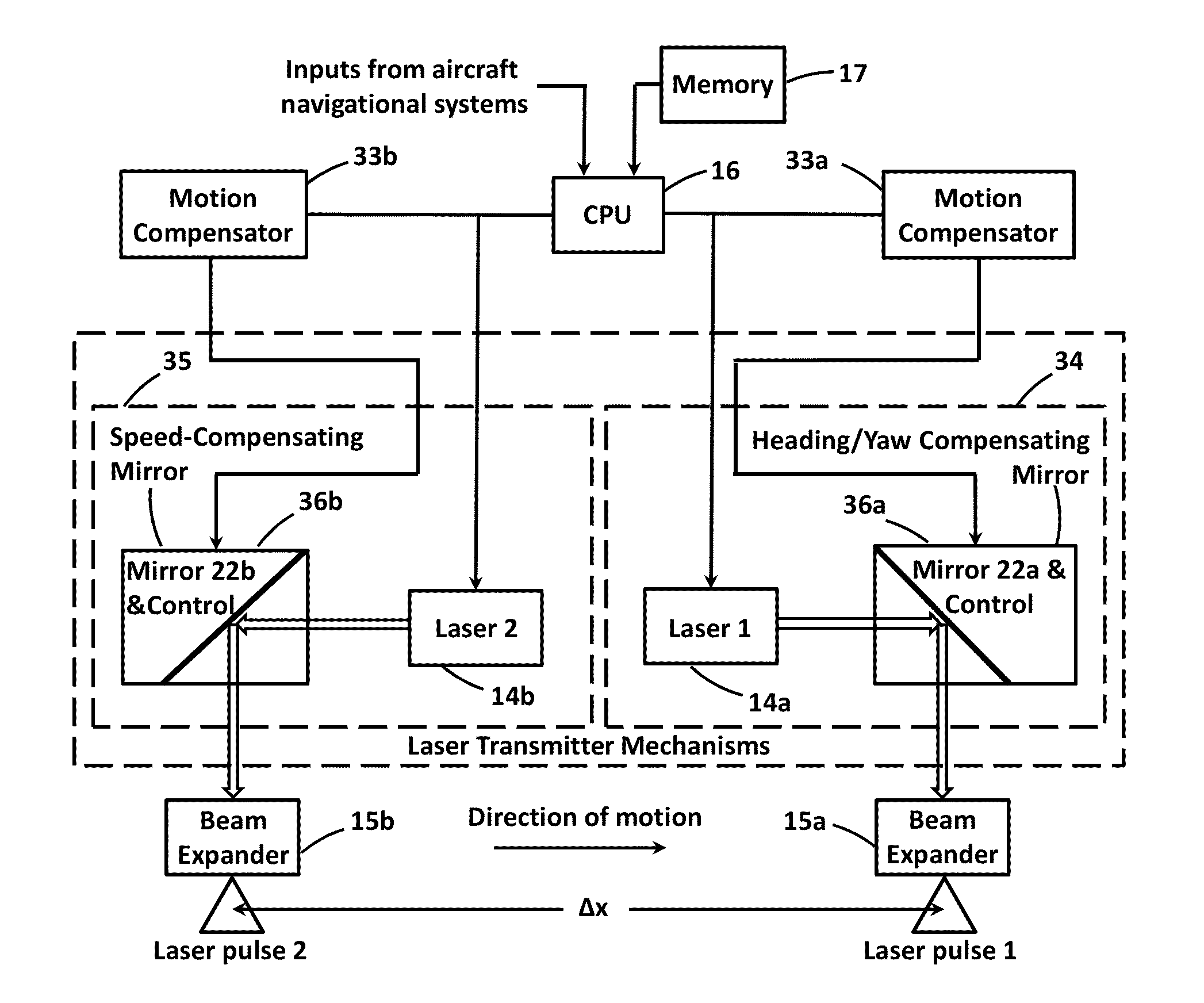
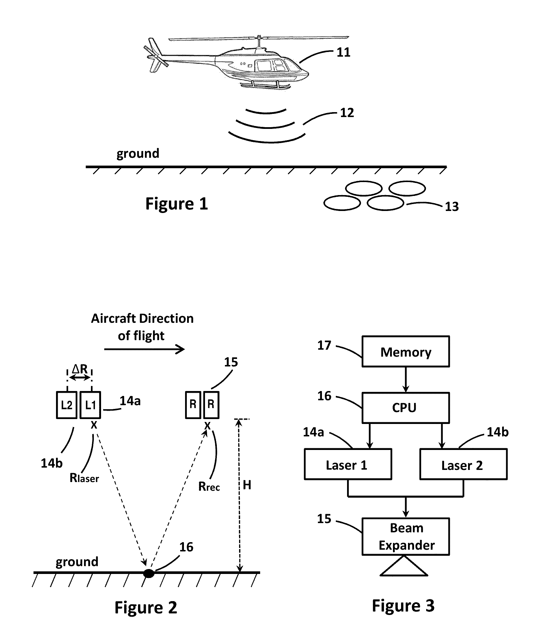
[0037]FIG. 1 shows an aircraft 11 moving to the right above the ground while transmitting a high intensity sound signal 12 toward the ground. Sound signal 12 is utilized to cause sufficient vibration deformation of the ground required for moving shearography to operate. The frequency of the sound is selected to cause the greatest vibration. Buried in the ground are anomalies 13 that may be, for example, archaeological remains. Aircraft 11 preferably flies at an altitude between 100 feet and 500 feet at a speed of 40 mph. However, the altitude and speed may be varied, along with other operating variables, for specific applications. Sound signal 12 will typically be transmitted toward the ground at an intensity of 150 decibels, or at another intensity level so that at ground level the sound intensity is in the order of 120 decibels. The intensity level may be varied, depending on the makeup of the ground, to provide the vibration deformations of the ground required for the moving shea...


PUM


Abstract

The invention allows a shearography system to successfully sense ground/surface vibrations while moving at aircraft speeds and altitudes. This is done by effectively making stationary the apparent location of a coherent laser beam illuminating an area on the ground/surface, and also effectively making stationary the apparent location of the aperture of an optical receiver which acquires pairs of sequential images captured and used for shearography. A different laser is used for capturing each of the two images, and the distance between the two lasers is adjusted based on a number of operational parameters. The adjustment of the distance causes the apparent locations of the transmitter and a receiver sub-aperture to remain the same and permits the moving shearography to work.

Description

RELATED APPLICATIONS[0001]This application claims the benefit of U.S. Provisional Application 61 / 435,633 filed Jan. 24, 2011, which is incorporated herein in its entirety by reference.GOVERNMENT RIGHTS[0002]The present invention was made with United States Government support under Contract No. N00014-07-C-0292 awarded by the United States Government, Department of the Navy. The United States Government has certain rights in this invention.FIELD OF THE INVENTION[0003]The invention relates generally to remote detection and imaging systems. More specifically the invention relates systems and methods for automatically detecting electromagnetic energy reflected or scattered from an object, and determining therefrom information about the object.BACKGROUND OF THE INVENTION[0004]In shearography, a surface being observed is illuminated by an expanding laser beam, and two time sequential images are captured of the surface of a part with an image-shearing camera. The first image is taken of th...

Claims


Application Information

Patent Timeline
Patent Type & Authority Patents(United States)
IPC IPC(8): G01B9/02
CPCG01B11/162G01C11/00
Inventor KOKOBUN, DANIELSAXER, CHRISTOPHER E
Owner BAE SYST INFORMATION & ELECTRONICS SYST INTERGRATION INC
Why Eureka
Try Eureka