Busbar connection system, switchgear unit, and method of transporting switchgear components

a busbar connection system and switchgear technology, applied in the direction of connection contact material, substation, coupling device connection, etc., can solve the problems of difficulty in installing at least some known busbars and/or switchgear, difficulty and/or cost, and parts transported with the busbar segments may become lost or misplaced

Active Publication Date: 2014-05-06
ABB (SCHWEIZ) AG
View PDF26 Cites 23 Cited by
  • Summary
  • Abstract
  • Description
  • Claims
  • Application Information

AI Technical Summary

Problems solved by technology

However, some parts transported with the busbar segments may become misplaced or lost if those parts are shipped independently of other parts.
Accordingly, an installation of at least some known busbars and / or switchgear may be hindered and / or may be difficult and / or expensive.

Method used


Image

  • Busbar connection system, switchgear unit, and method of transporting switchgear components
  • Busbar connection system, switchgear unit, and method of transporting switchgear components
  • Busbar connection system, switchgear unit, and method of transporting switchgear components

Examples


Embodiment Construction

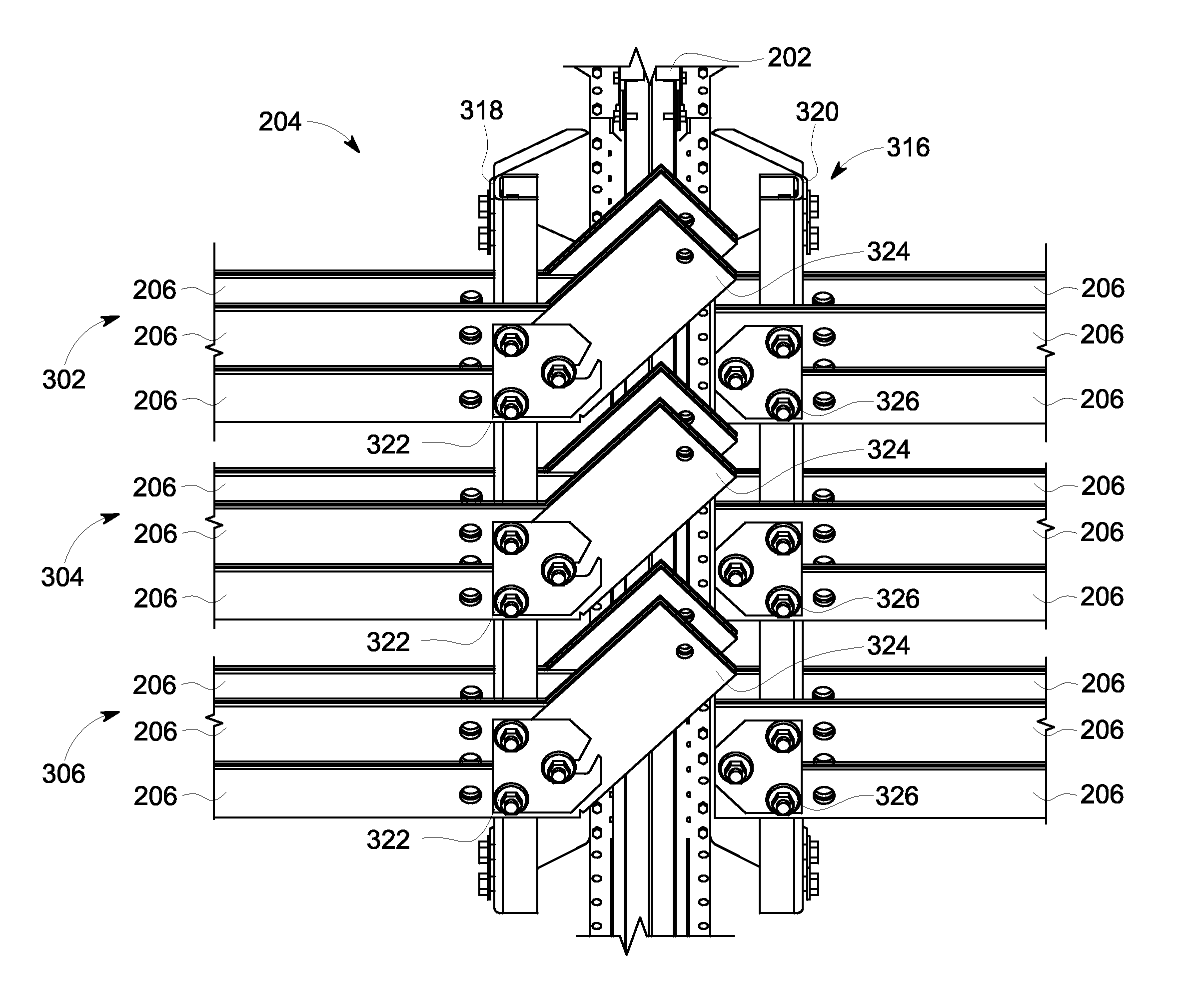
[0017]Exemplary embodiments of a busbar connection system, a switchgear unit, and a method of transporting switchgear are described herein. The busbar connection system includes a plurality of busbar segments that are coupled together to form one or more busbars arranged in one or more busbar phases. In one embodiment, a first phase of busbar segments (a “first busbar phase”) includes a first busbar segment, a second busbar segment, a third busbar segment, and a fourth busbar segment. A mounting component is coupled to the first busbar segment and to the second busbar segment. A retaining component is coupled to the third busbar segment and to the fourth busbar segment. A connecting member is pivotally coupled to the first busbar segment and the second busbar segment by the mounting component.

[0018]In an embodiment, the partially assembled busbar connection system is transported to a predetermined location, such as an installation site, to complete the assembly. At the installation ...


PUM

PropertyMeasurementUnit
currentaaaaaaaaaa
poweraaaaaaaaaa
electricalaaaaaaaaaa

Abstract

A busbar connection system for coupling a first busbar segment to a second busbar segment includes a mounting component defining a slot and configured to be coupled to the first busbar segment, a retaining component configured to be coupled to the second busbar segment, and a connecting member including a first end and an opposing second end. The first end is configured to be coupled to the mounting component and the second end is configured to be coupled to the retaining component. The busbar connection system also includes a pivot member configured to be operatively coupled to the first end and shaped to be received within the slot. The pivot member enables the connecting member to pivot about the mounting component.

Description

BACKGROUND OF THE INVENTION[0001]The present application relates generally to power systems and, more particularly, to a busbar connection system, a switchgear unit, and a method of transporting switchgear components.[0002]At least some known circuit breakers are included within electronic or magnetic trip devices that programmably interrupt a current provided to a load. The trip devices and the circuit breakers may be installed in switchgear or other power distribution systems that provide electricity to important revenue-generating machinery and / or to machines or devices that are highly desirable to maintain in operation.[0003]Some known switchgear are installed at a customer site to protect the machines or devices therein. The switchgear typically include one or more busbars that enable current to flow to a load. At least some known busbars are transported to the installation site in a plurality of busbar segments. The busbar segments are connected together, for example, by a tec...

Claims


Application Information

Patent Timeline
Patent Type & Authority Patents(United States)
IPC IPC(8): H01R43/00H01R3/00H01R4/60H02B1/20
CPCH02B1/308H02B13/005H01R4/60H02B1/20H01R35/04H01R25/162Y10T29/49117
Inventor VALENZUELA, RUBEN
Owner ABB (SCHWEIZ) AG
Why Eureka
Try Eureka