Auto-focus image system

a technology of image system and autofocus, which is applied in the field of autofocus electronically captured images, can solve the problems of small detection point group, ineffective technique, and inconvenient contrast technique for motion video

Inactive Publication Date: 2014-05-13
TAY HIOK NAM
View PDF5 Cites 11 Cited by
  • Summary
  • Abstract
  • Description
  • Claims
  • Application Information

AI Technical Summary

Benefits of technology

[0008]An auto focus image system that includes a pixel array coupled to a focus signal generator. The pixel array captures an image that has at least one edge with a width. An edge is a group of a plurality of pixels arrayed side-by-side in a direction and a gradient signal in said direction is either all-positive or all-negative over the plurality of pixels. The generator generates a focus signal that is a function of the edge width and various statistics of edge width. The generator may eliminate an edge having an asymmetry of a gradient of an image signal. The generator may also eliminate an edge that fails a template for an associated peaking the gradient. Edge corruption / partial corruption may be detected. Partially corrupted edge may have edge width calculated by relying more on the side that is not corrupted and less on the side that is corrupted. Edge or edge side corruption may be detected by detecting a presence of an adjacent edge of the opposite sign.

Problems solved by technology

Although acceptable for still pictures the contrast technique is not suitable for motion video.
Having a small group of detection points is prone to error because noise may be superimposed onto one or more points.
This technique is also ineffective if the detection points do not coincide with an image edge.
This can be problematic in dim settings where the image light intensity is already low.

Method used


Image

  • Auto-focus image system
  • Auto-focus image system
  • Auto-focus image system

Examples


Embodiment Construction

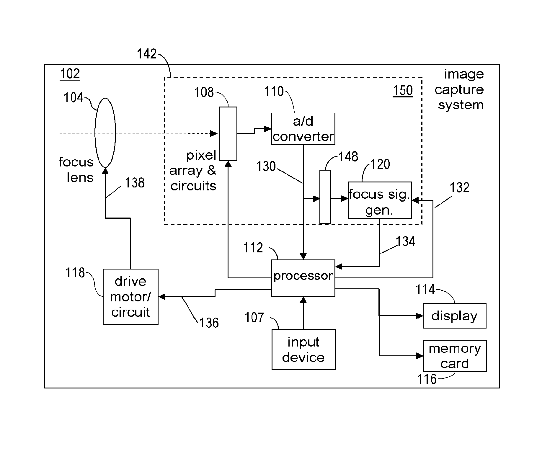
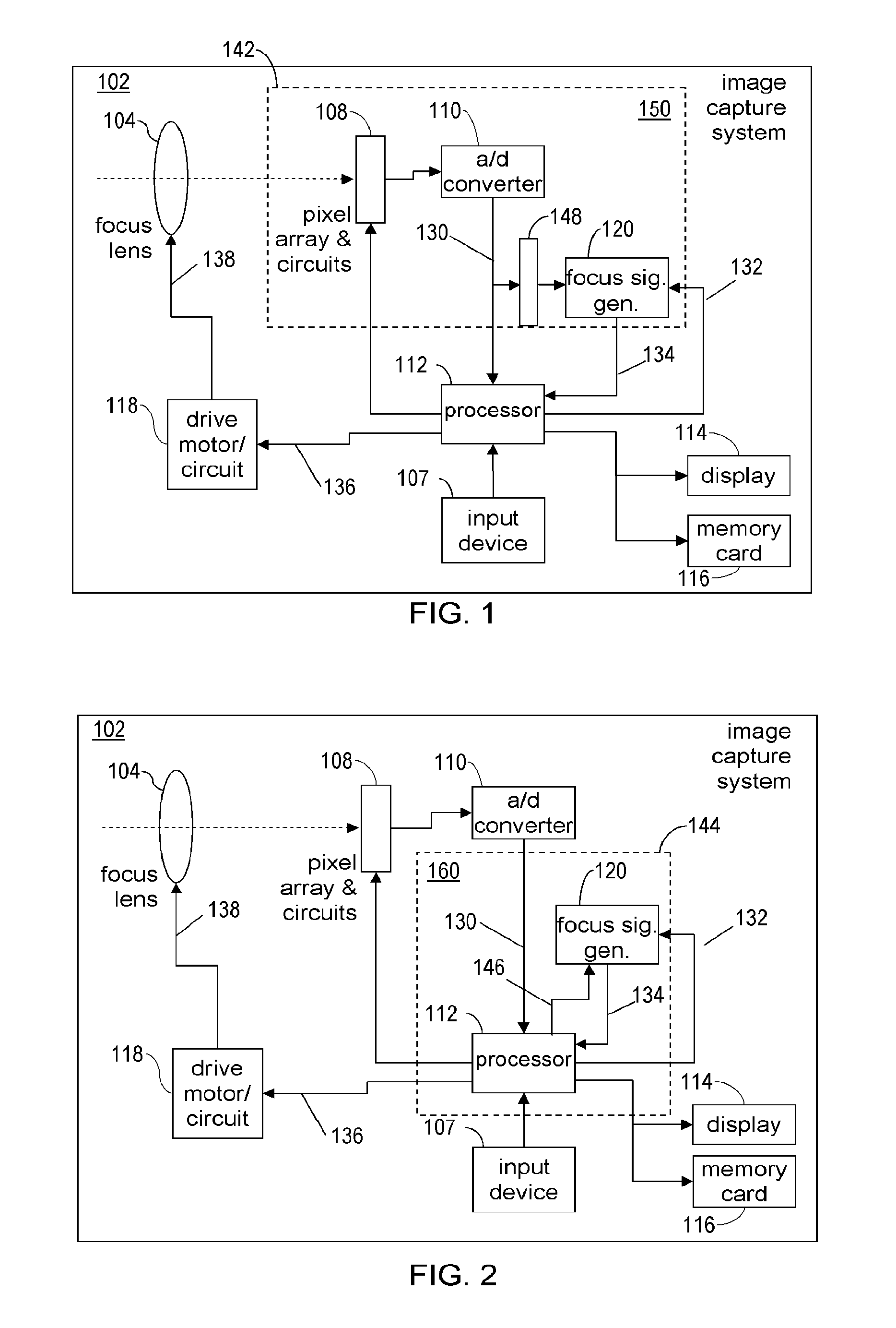
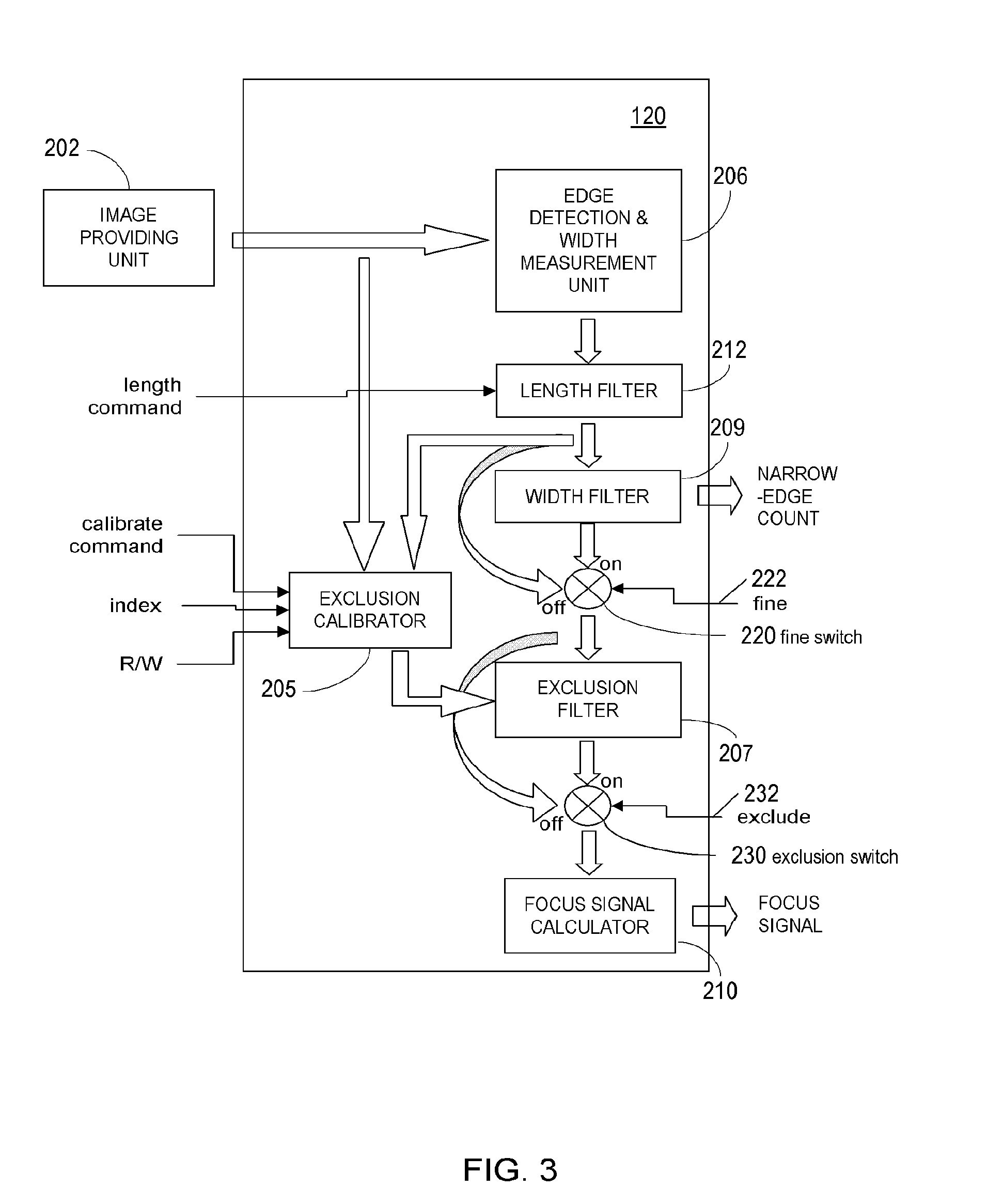
[0080]Disclosed is an auto focus image system that includes a pixel array coupled to a focus signal generator. The pixel array captures an image that has at least one edge with a width. The focus signal generator may generate a focus signal that is a function of the edge width and / or statistics of edge widths. An auto focus image system that includes a pixel array coupled to a focus signal generator. The pixel array captures an image that has at least one edge with a width. The generator generates a focus signal that is a function of the edge width and various statistics of edge width. The generator may eliminate an edge having an asymmetry of a gradient of an image signal. The generator may also eliminate an edge that fails a template for an associated peaking in the gradient. A processor receives the focus signal and / or the statistics of edge widths and adjusts a focus position of a focus lens. The edge width can be determined by various techniques including the use of gradients. ...


PUM


Abstract

An auto focus image system that includes a pixel array coupled to a focus signal generator. The pixel array captures an image that has at least one edge with a width. The focus signal generator may generate a focus signal that is a function of the edge width and / or statistics of edge widths. A processor receives the focus signal and / or the statistics of edge widths and adjust a focus position of a focus lens. The edge width can be determined by various techniques including the use of gradients. A histogram of edge widths may be used to determine whether a particular image is focused or unfocused. A histogram with a large population of thin edge widths is indicative of a focused image. Edge corruption / partial corruption may be detected. Partially corrupted edge may have edge width calculated by relying more on the side that is not corrupted and less on the side that is corrupted. Edge or edge side corruption may be detected by detecting a presence of an adjacent edge of the opposite sign.

Description

REFERENCE TO RELATED APPLICATION[0001]This Application claims priority to U.S. Provisional Application No. 61 / 331,732, filed on May 5, 2010.BACKGROUND OF THE INVENTION[0002]1. Field of the Invention[0003]The subject matter disclosed generally relates to auto-focusing electronically captured images.[0004]2. Background Information[0005]Photographic equipment such as digital cameras and digital camcorders may contain electronic image sensors that capture light for processing into still or video images, respectively. Electronic image sensors typically contain millions of light capturing elements such as photodiodes.[0006]Many image capturing devices such as cameras include an auto-focusing system. The process of auto-focusing includes the steps of capturing an image, processing the image to determine whether it is in focus, and if not, generating a feedback signal that is used to vary a focus position of a focus lens. There are two primary auto-focusing techniques. The first technique i...

Claims


Application Information

Patent Timeline
Patent Type & Authority Patents(United States)
IPC IPC(8): G06K9/40H04N5/232
CPCH04N5/23212G06T7/00G06T5/003H04N23/673H04N23/635
Inventor TAY, HIOK, NAM
Owner TAY HIOK NAM
Why Eureka
Try Eureka