Technique for dual homing interconnection between communication networks

a communication network and dual node technology, applied in data switching networks, frequency-division multiplexes, instruments, etc., can solve the problems of conventional dual node homing techniques, limited local network operators' possibilities, and inapplicability to vpls networks, so as to prevent traffic duplication/loops and protect traffi

Active Publication Date: 2014-05-13
ECE TELECOM LTD
View PDF17 Cites 1 Cited by
  • Summary
  • Abstract
  • Description
  • Claims
  • Application Information

AI Technical Summary

Benefits of technology

[0009]It is therefore the object of the present invention to provide a new, simpler dual homing technique, being capable of ensuring sufficient protection of traffic between the networks interconnected by a dual homing configuration and preventing traffic duplication / loops.
[0026]the second node group allows transparently transmitting there-through control messages of the protocol in both directions, whenever said control messages are issued by the first node group;
[0030]The proposed dual home solution allows easily organizing traffic protection and loop prevention in a dual home configuration “just from the side of your own network”. It can be done by a network provider by enabling the group (one node or a pair of edge nodes) of its own network to utilize, say, a G.8032-type protocol, while not bothering at all about deployment of the protocol to the opposite pair of edge nodes which are situated in a remote network. The preferred additional condition will be used then to ensure that the mentioned ring-like path connecting the pair of local edge nodes via the opposite (remote) pair of edge nodes, will become a tunnel transparently conveying there-through control messages in order to establish free circulation of the G.8032-type messages in the ring. It should be noted, however, that this additional condition is not always required; there may be a case where the tunnel transparently conveying control messages does not exist (for example, when the first node group—and only the first node group—comprises a root node / a master node of the protocol and the decisions are actually made based on the control messages issued at the sole / root node of the first group).
[0040]It should be noted that the proposed dual homing interconnection is advantageous for layer 2 Ethernet networks, and especially for SVLANs (Provider Service virtual Local Access Networks) or VPLS (virtual private LAN service domains). With VPLS, Ethernet packets arriving from an access network are encapsulated in a multi-protocol label switching (MPLS) format, based on which they are forwarded across a provider network toward the required remote sites. The use of MPLS enables optimal utilization of network resources, for example utilizing fast rerouting (FRR) and scalability. VPLS architecture implements full mesh connectivity between the provider edge nodes (PE) that connect the customer access networks, thus allowing communication of each access network with any other access network belonging to the same group of VPLS domains. Each PE-PE path carrying VPLS traffic is called a pseudo-wire (PW).

Problems solved by technology

However, since the spanning tree does not have visibility as to the internal structure of the ring, the spanning tree cannot block links on the Ethernet ring network.
The important drawback of the above-mentioned proposal and of the other discussed prior art solutions as well is that all nodes of the dual homing structure (IR ring in the case of the above-mentioned contribution) must actively exchange G.8032 messages there-between.
Such a requirement seriously limits possibilities of a local network operator, who considers providing a dual homing connection with a remote network, since a loop protocol cannot be ensured by the local facilities.
Another drawback of conventional dual homing techniques stems from their intrinsic feature to provide protection to traffic carried between two interconnected networks.
However, it is not applicable to VPLS networks.

Method used


Image

  • Technique for dual homing interconnection between communication networks
  • Technique for dual homing interconnection between communication networks
  • Technique for dual homing interconnection between communication networks

Examples


Embodiment Construction

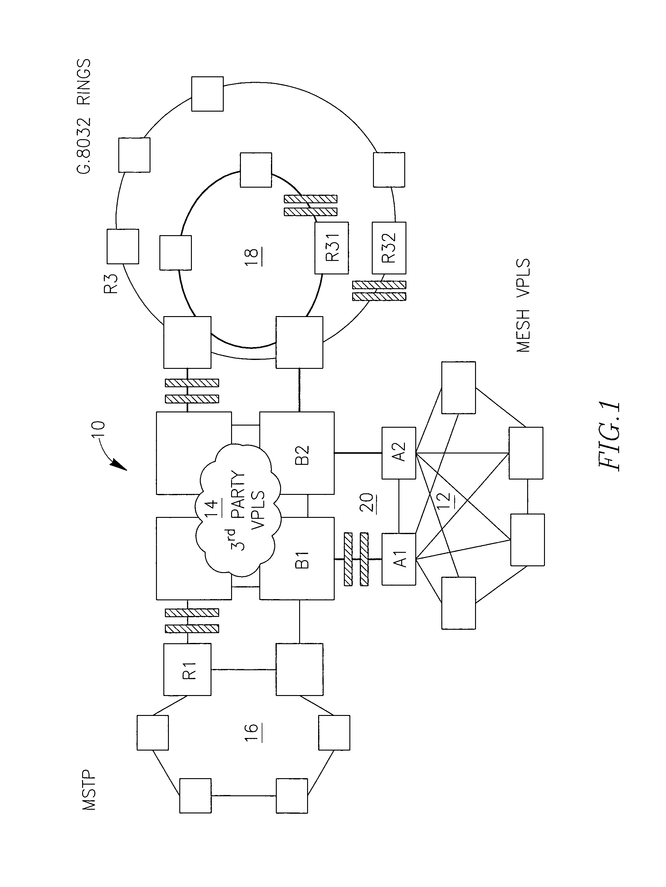
[0071]FIG. 1 illustrates an example of a multi-domain network 10 comprising a local access network 12 (say, a mesh VPLS network), a third party network 14 being an VPLS network, a ring-like MSTP network 16 and a number of ring networks 18 which can be protected by G.8032 protocol. Network 12 is interconnected with network 14 via a dual homing configuration A1, A2, B1, B2 (schematically marked 20) where nodes (gateways, GWs) A1 and A2 belong to network 12. They can be called a first nodes group. Nodes (GWs) B1, B2 of 20 belong to network 14 and can be called a second nodes group. Other networks are interconnected with the network 14 in a similar manner.

[0072]FIG. 1 shows that each of the ring networks 18, protected by G.8032, comprises a root node (R31, R32) which keeps open (logically blocked for data traffic) one of the links connected to the root node. The open links are called Ring Protection Links (RPL) and are schematically marked with two parallel thick hatched lines symbolizi...


PUM


Abstract

A dual homing technique for ensuring loop free transmission of traffic between telecommunication networks such as VPLS by utilizing a loop protocol in the dual homed connection. The technique also provides selective handling of VPLS data streams protected and non-protected by the dual homing loop protocol.

Description

FIELD OF THE INVENTION[0001]The present invention relates to a technology of dual home (dual node) interconnection between various communication networks, in particular the invention may be applied to pure Ethernet Layer 2 (L2) networks, VPLS networks or a combination there-between.BACKGROUND OF THE INVENTION[0002]The technique of dual home / dual homing interconnection of L2 communication networks was developed for providing protection to the traffic carried between the networks. The most important requirement to the dual homing techniques is preventing traffic duplication and traffic loops which might occur due to intrinsic redundancy of the dual homing configurations. Various solutions of the technique are presently known in the prior art.[0003]U.S.2008219156A describes a communication network protection system made up of interconnected networks, at least one of which has an automatic control plane (for example ASTM) comprising terminal interconnecting nodes, termed primary nodes. ...

Claims


Application Information

Patent Timeline
Patent Type & Authority Patents(United States)
IPC IPC(8): H04L12/28
CPCH04L12/437H04L12/4637H04L12/462
Inventor SERGEEV, ANDREWKUGEL, ALEXANDERAGMON, GIDEONCOHEN, ROTEM
Owner ECE TELECOM LTD
Why Eureka
Try Eureka